Architectural model production process
1. Preparation
1、software tools
(1) QGIS:This document is based on3.18 write
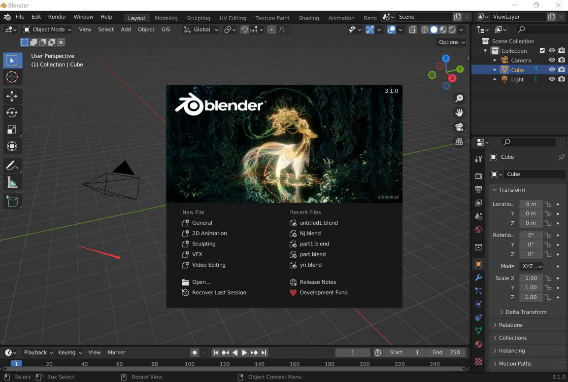
(2) Blender:This document is based on3.1.0 write
(3) BlenderGIS:forBlender plugin,Download address (Install BlenderGIS Methods are available on Baidu)
2、Data requirements
(1) Data format:ESRI Shapefile
(2) Coordinate system:WGS84 WebMercator(EPSG: 3857)
(3) Data type: area data
(4) Data attribute: must contain the attribute of building height, and the attribute name must be in English
3、Data preprocessing【Optional】
(1) If there is a lot of building data, you can choose to split it into multiple files through attribute filtering;
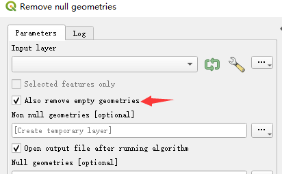
(2) Try to delete none in advancegeometry data, inQGIS Select tools【Remove null geometries】,Select the corresponding layer and check【Also remove empty geometries】
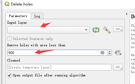
(3)The holes existing in the building data can be processed inQGIS selected in【Delete holes】,Select the corresponding layer and set the maximum area of holes to be deleted, the default value"0"That is, delete all holes.
4、Blender Environmental preparation
(1)Delete scene default content:Click on the blank space-【A】-【Delete】
(2)Set up scene camera:【N】-【View】-expand"End"Value, in case not all objects in the scene can be displayed.
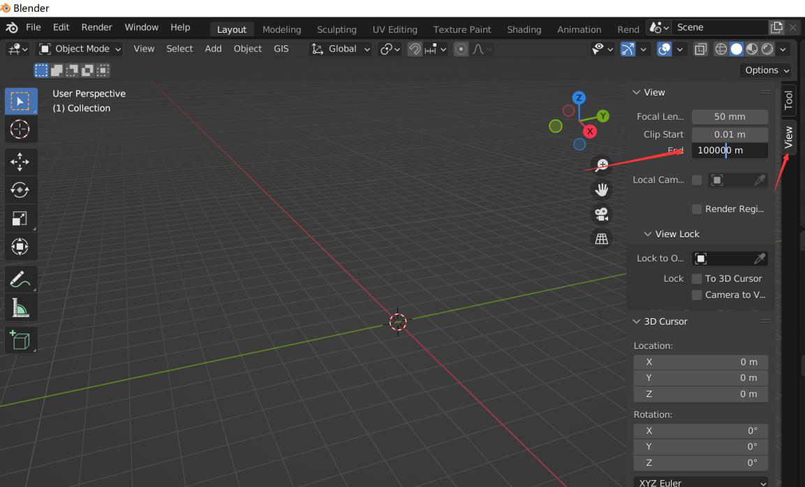
(3)Switch rendering mode:The default is the second"Entity mode display",After adding the texture, you can switch to"Material preview mode display"。

2. Model building process
1、Automatically generate models
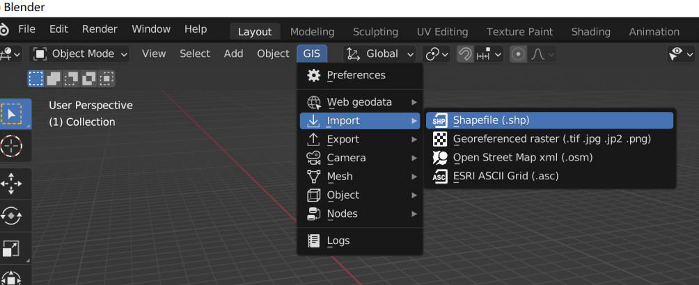
(1)import shp document
【GIS】-【Import】-【Shapefile】,Choose localshp file and confirm the import.
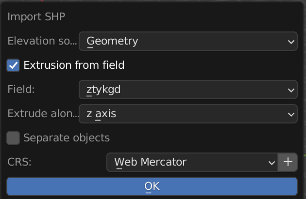
(2)Set build parameters
exist"Import SHP"In the dialog box, check【Extrusion from field】,"Field"Select the attribute corresponding to the building height;"CRS"choose【Web Mercator】,Click【OK】,The building model will be built automatically.
2、Dealing with model holes
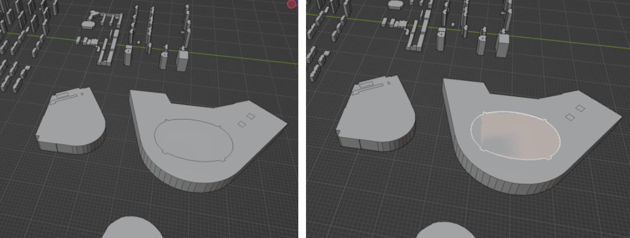
(1)Select the top surface of the hole
i. Select edit mode and select face picking
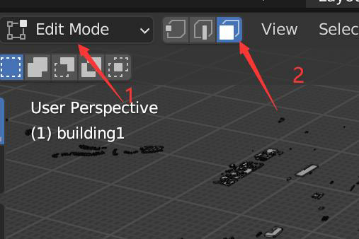
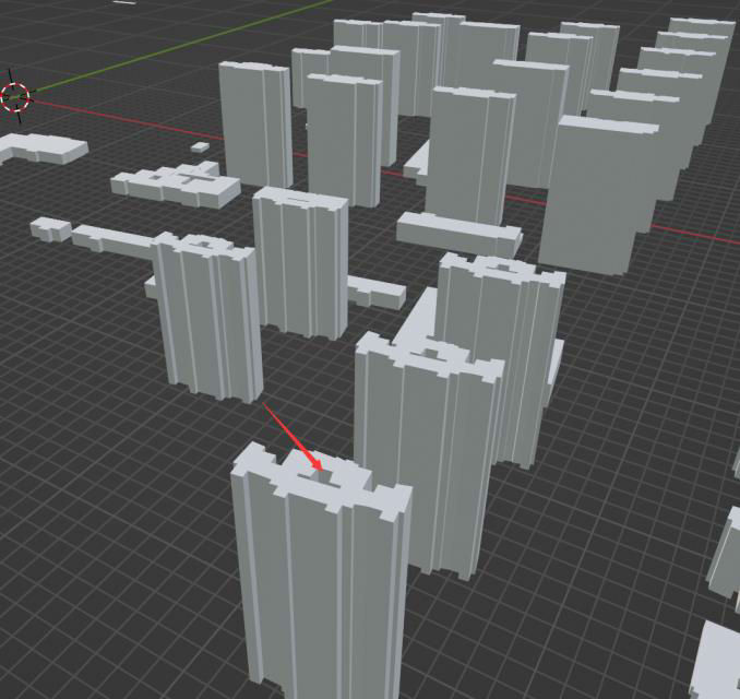
ii. Click on the top surface of the hole on the model, as shown below:
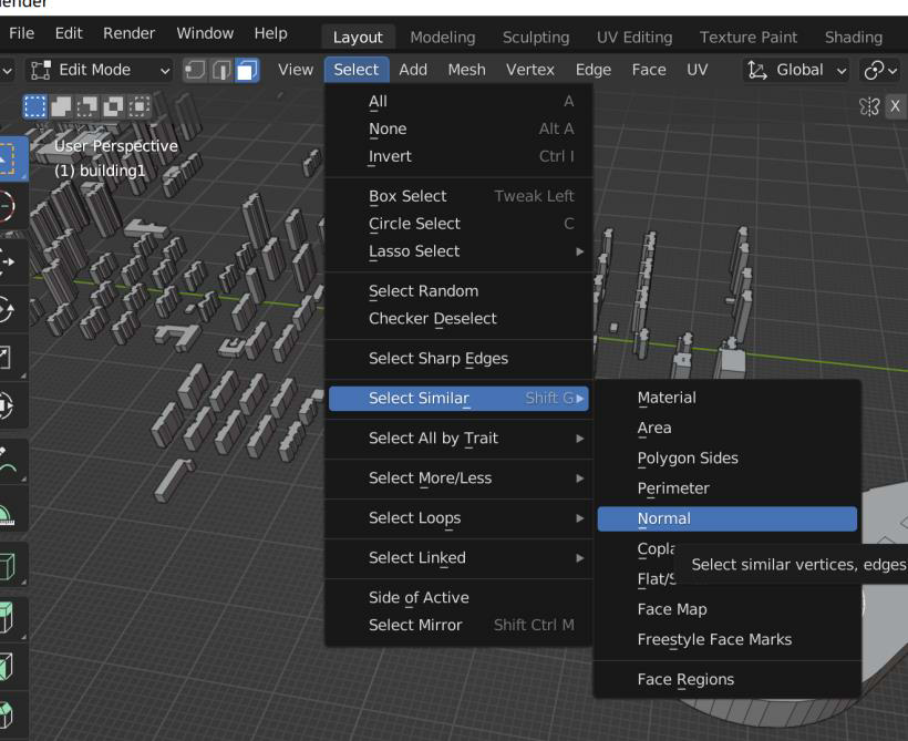
(2)Select all top faces of holes
【Select】-【Select Similar】-【Normal】
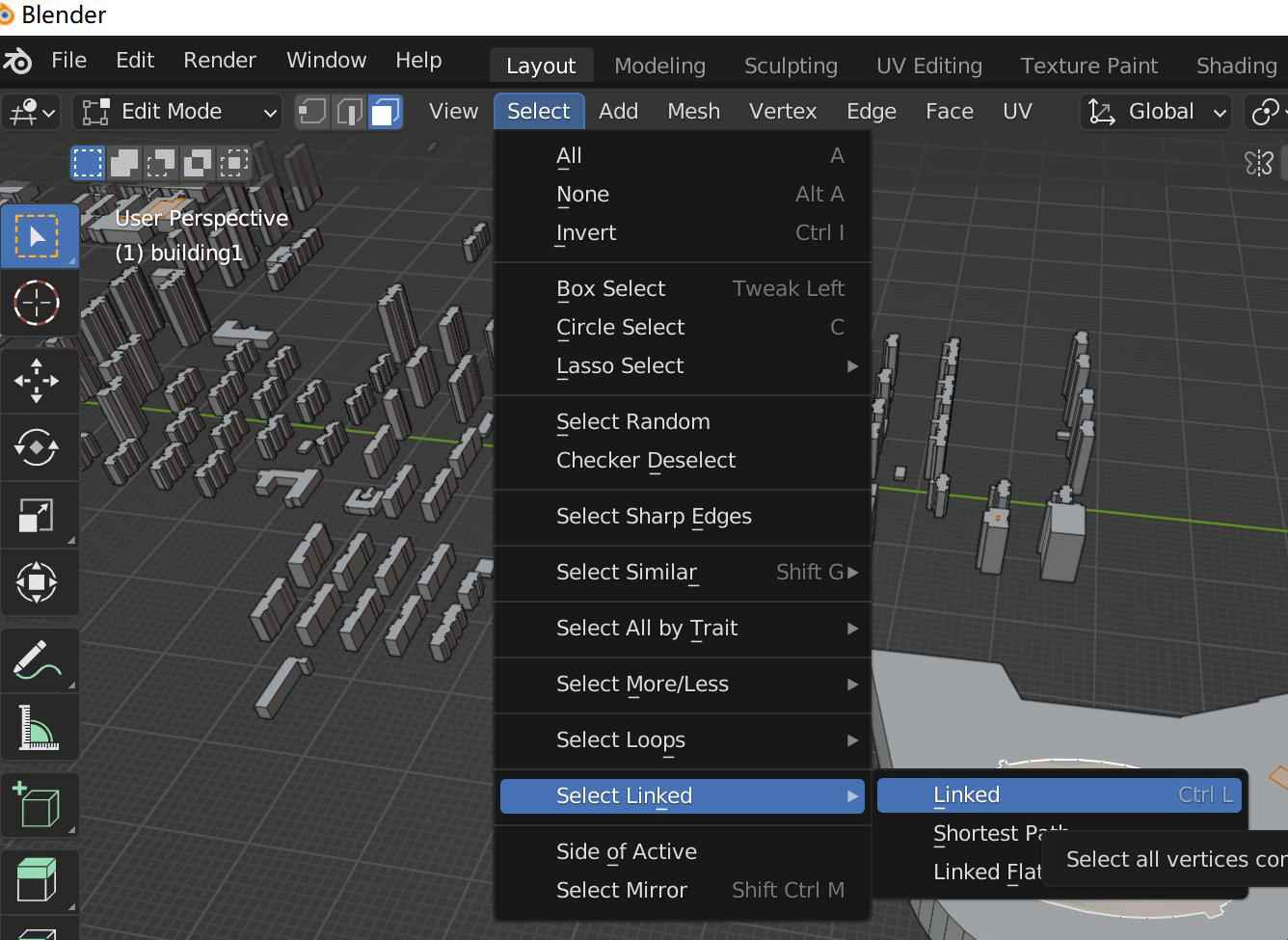
(3)Select hole model
i. 【Select】-【Select Linked】-【Linked】
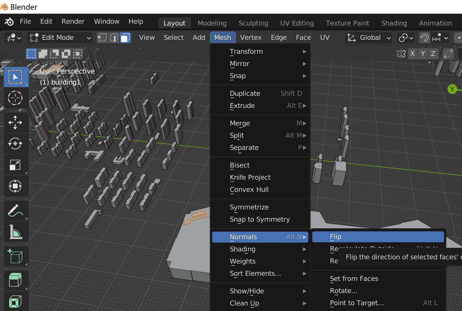
ii. 【Mesh】-【Normals】-【Flip】
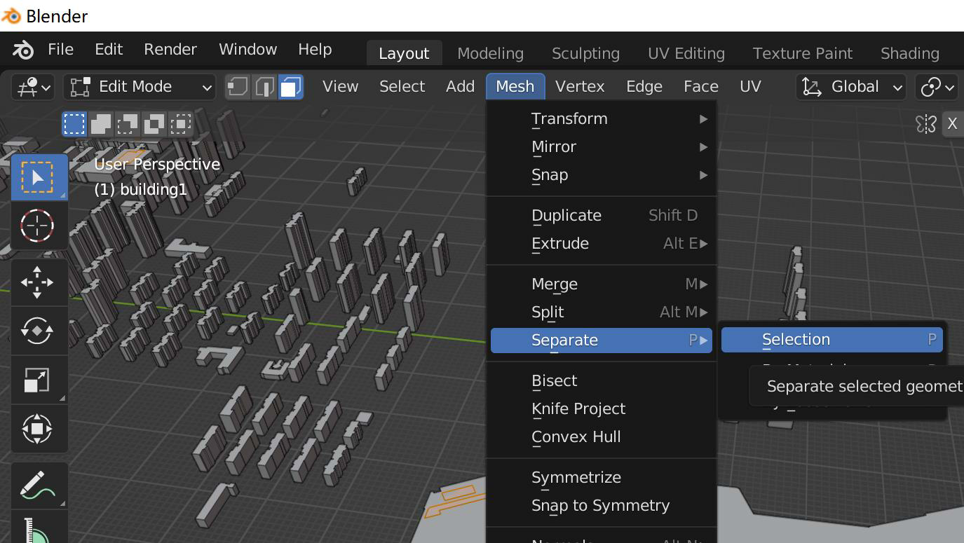
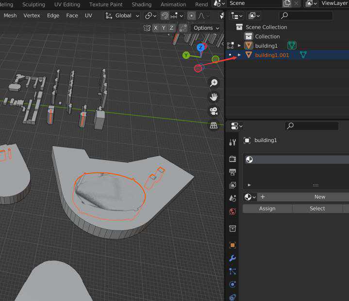
iii. 【Mesh】-【Separate】-【Selection】,The hole model separation will be completed and the name is"XXXX.001"
(4)Remove hole model
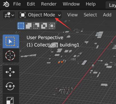
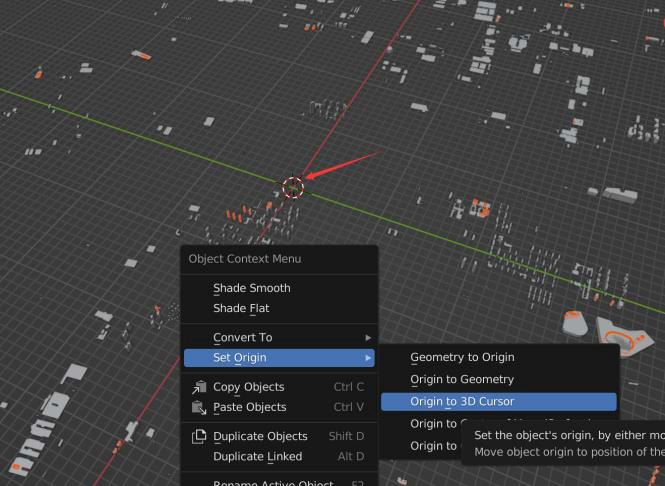
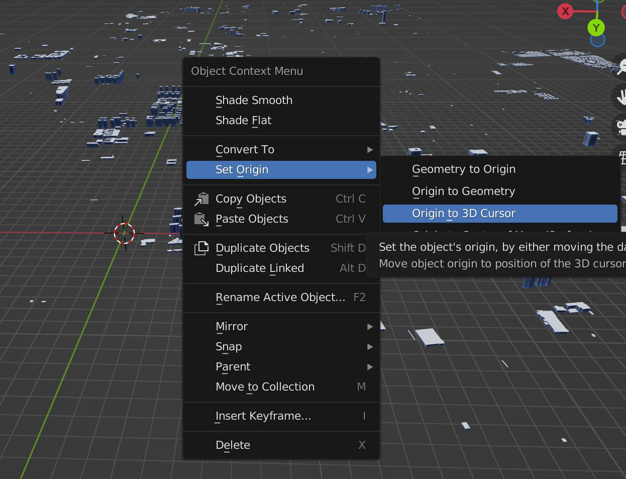
i. Keep"XXXX.001"Select the state and then switch to【Object Mode】,Right-click in the model display area,【Set Origin】-【Origin to 3D Cursor】
ii. Switch to zoom mode and followz Stretch the axis upward (blue axis)
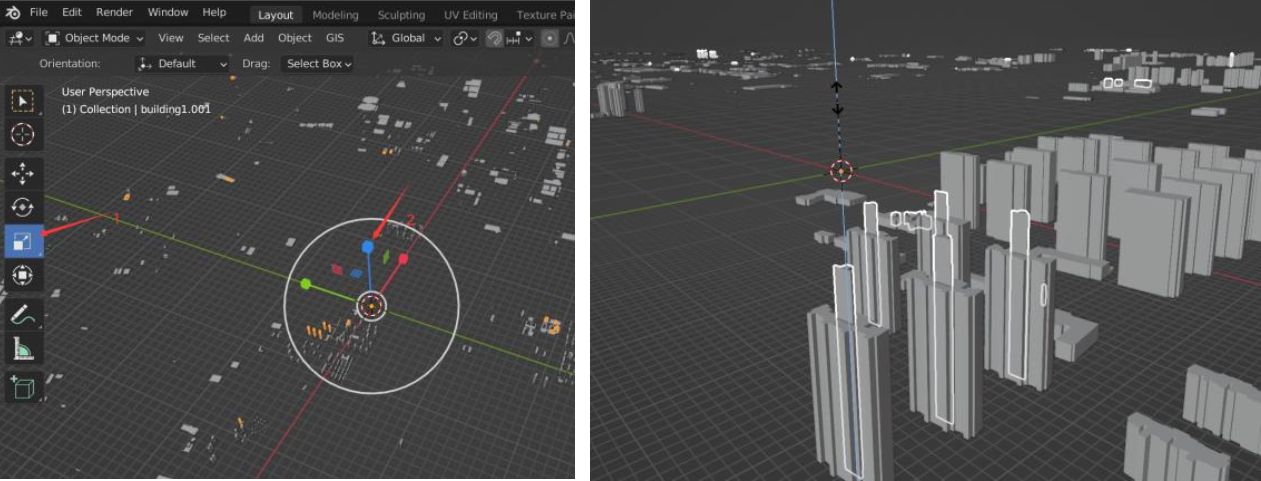
iii. In the outline view, select the automatically generated model and click【Modifier Properties】-【Add Modifier】-【Boolean】
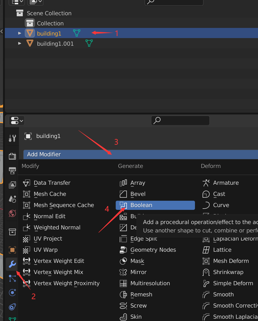
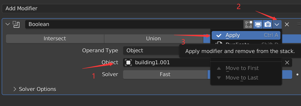
iv. "Object"Select hole model"XXXX.001",【Apply】,The hole processing is now complete.
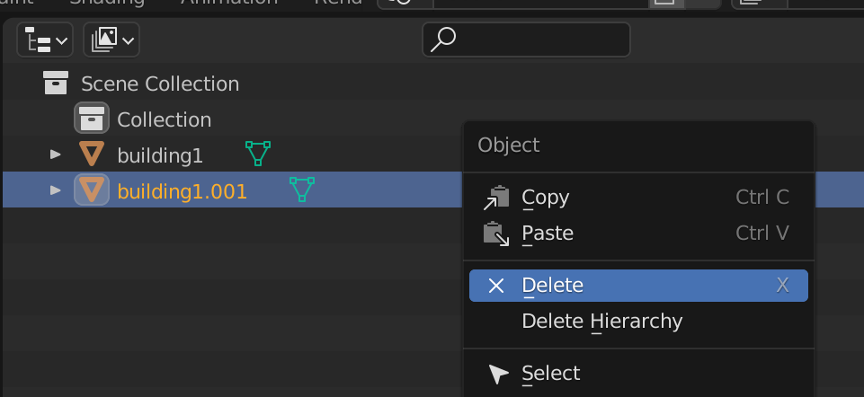
v. In the outline view, right-click"XXXX.001",choose【Delete】,delete"XXXX.001",Keep only the building models you need.
3、Process the top material
(1)Create top material
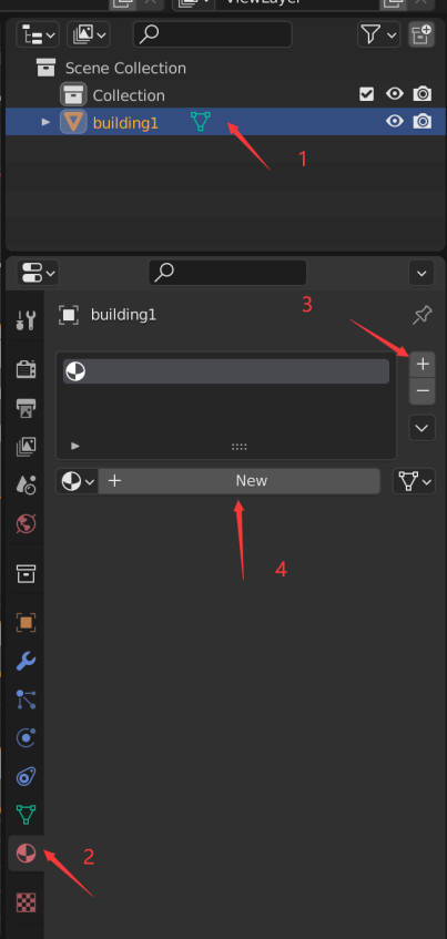
i. Keep the building model selected and click【Material Properties】-【+】-【New】
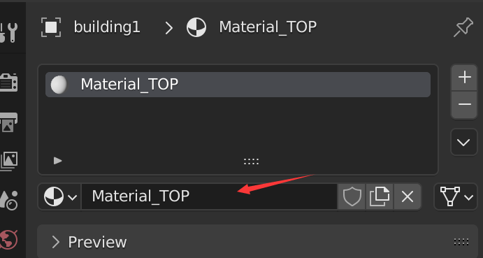
ii. Set the material name of the top of the building to【Material_TOP】
(2)Apply top material
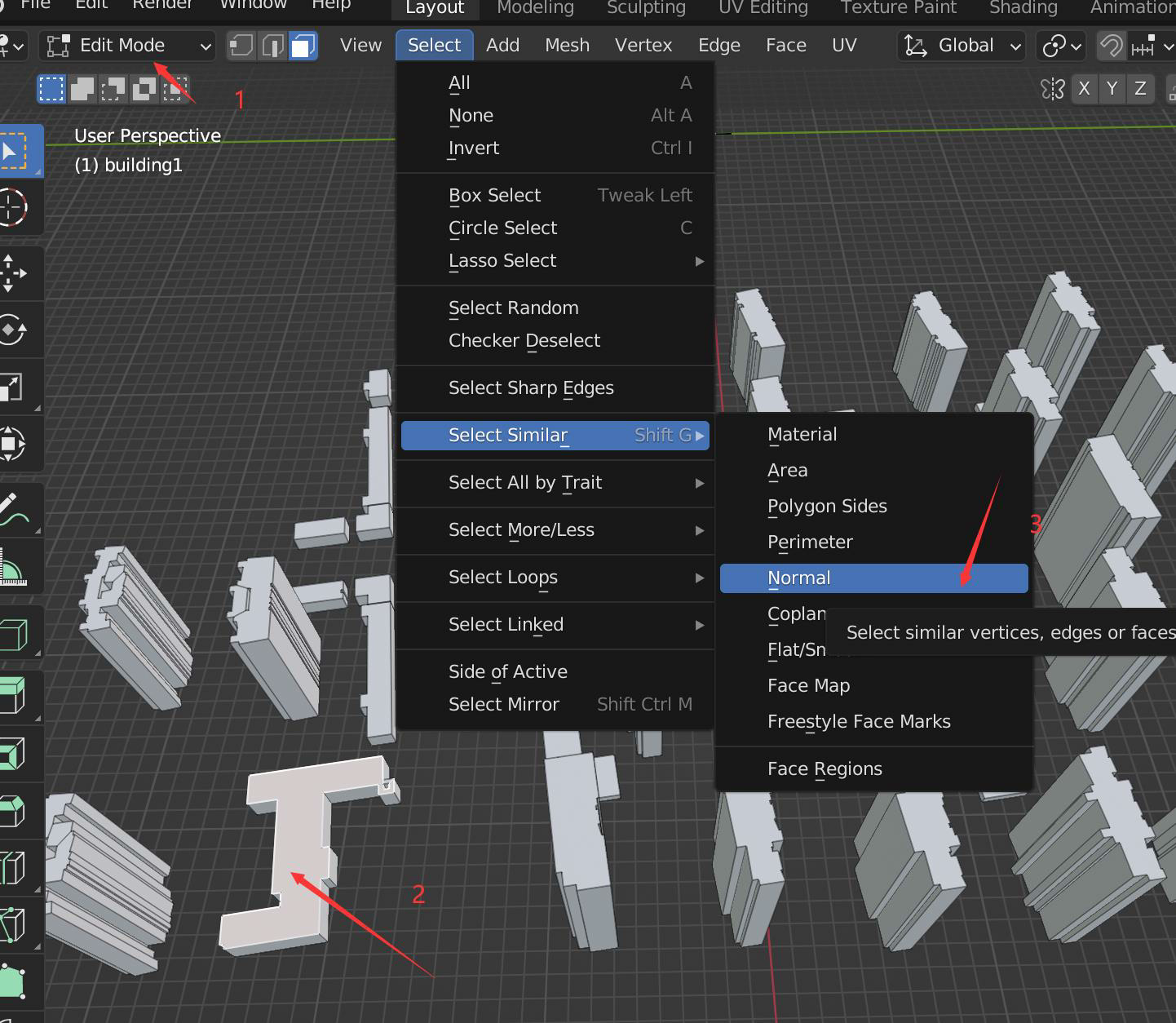
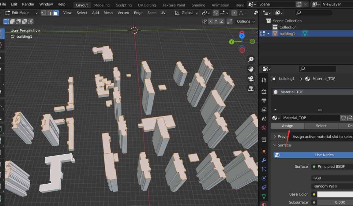
i. Switch to edit mode, enter face selection mode, click to select a building top face, and then【Select】-【Select Similar】-【Normal】Select all building top faces.
ii. Click【Assign】,Apply material to building top surface
4、Processing wall materials
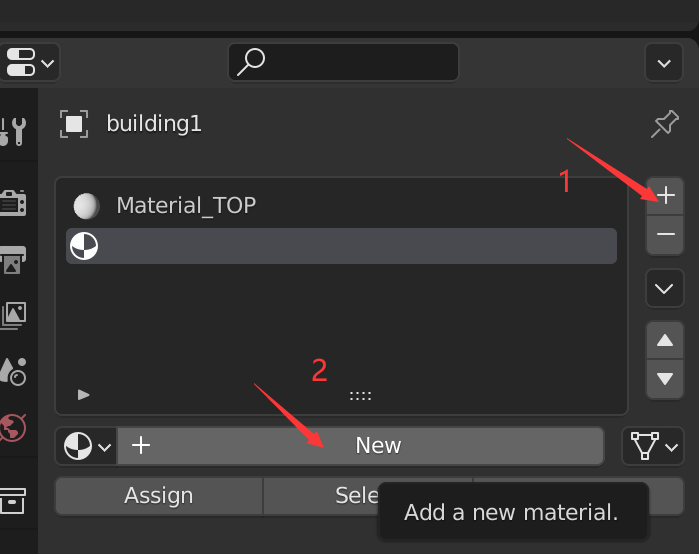
(1)Create wall material
i. Click【Material Properties 】in【+ 】-【New】,Set wall material name【Material_WALL】(The material name must containWALL)
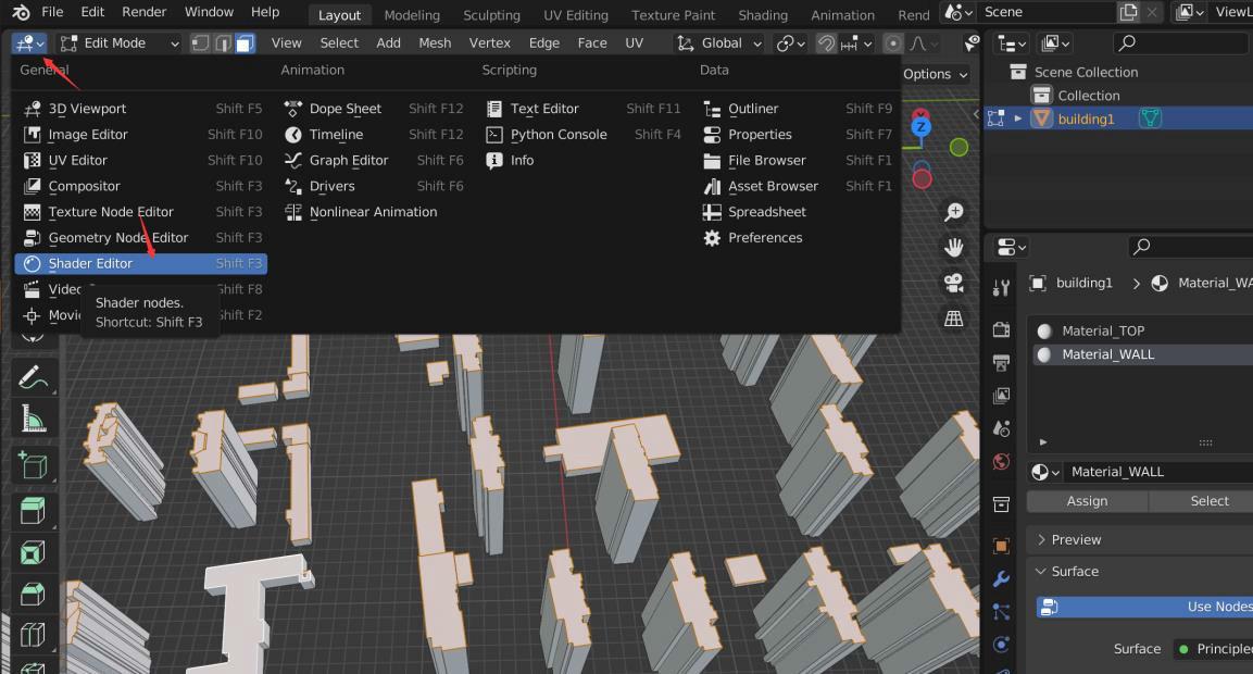
ii. Adjust to shader editing mode and select【Shader Editor】
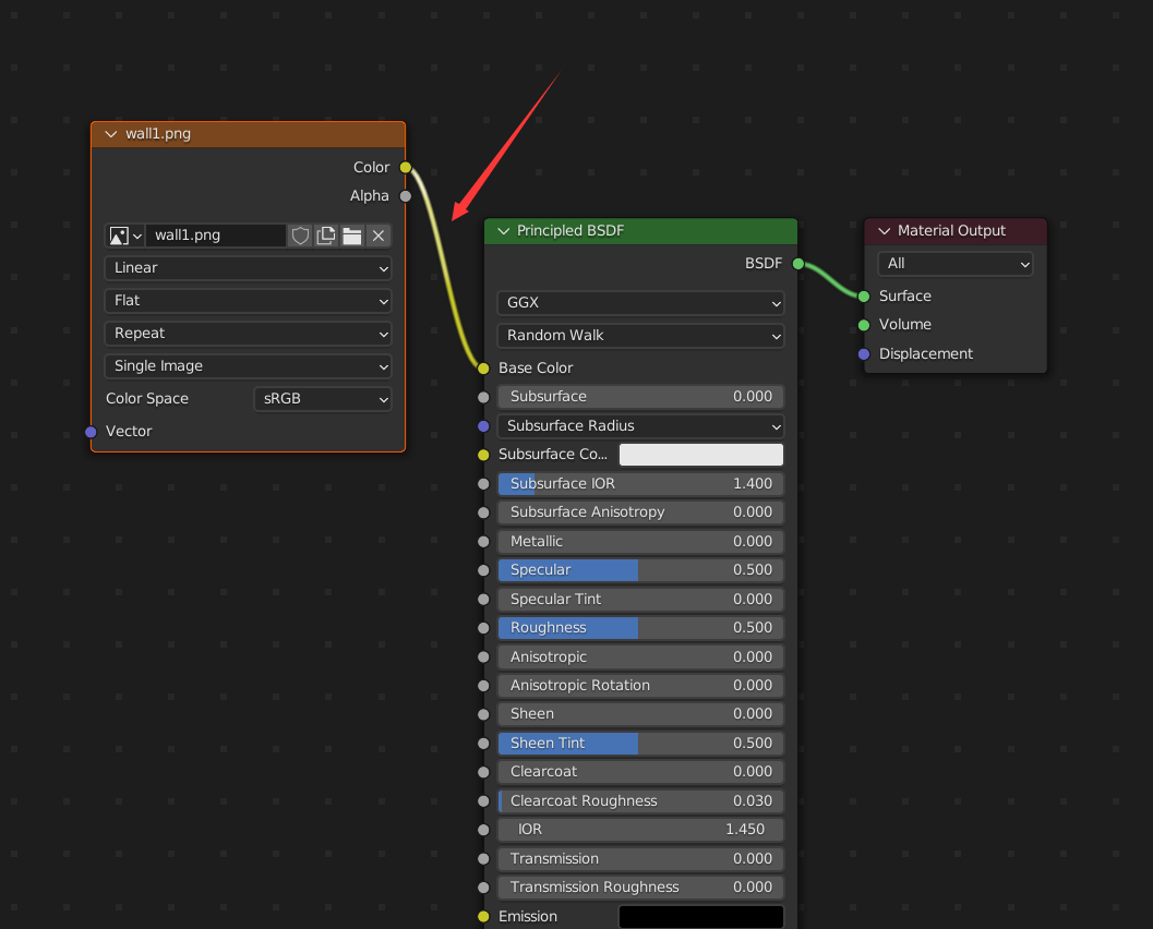
iii.Change the local image (wall1.png)Drag it into the window to form a node, and output this node【Color】Connect to【Base Color】
(2)Apply wall material
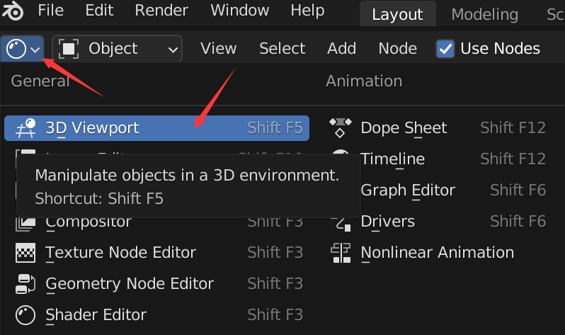
i. switch back3D view, select【3D Viewport】
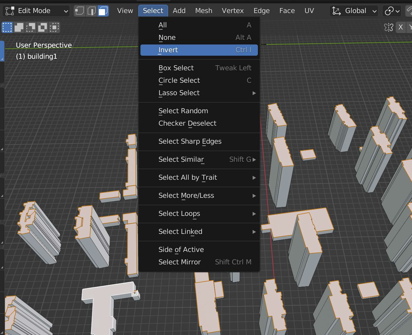
ii. Continue steps3, in the state of selecting the top surface,【Select】-【Invert】,Select all building walls by inverting the selection.
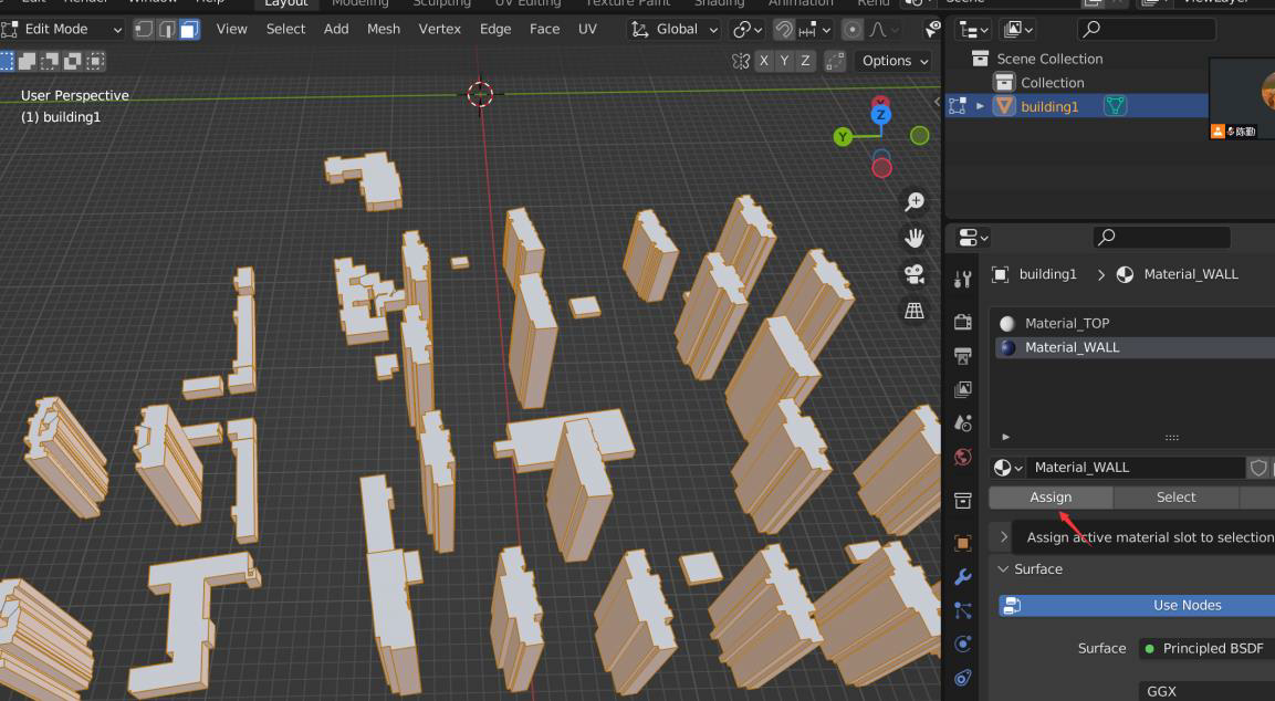
iii. Click【Assign】,Apply materials to building walls
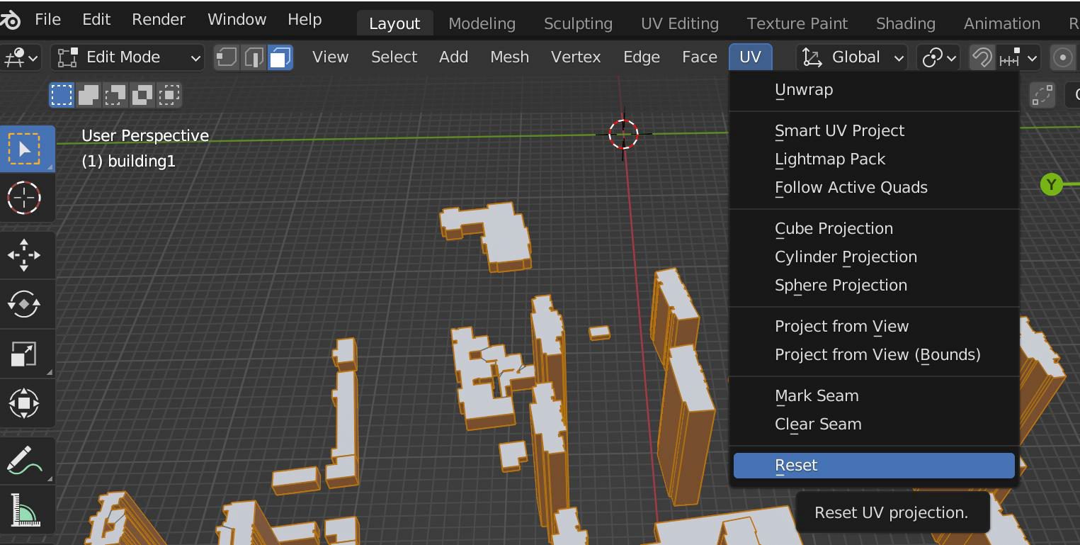
iv. Make wallUV set up,【UV】-【Reset】
5、Adjust model origin
i. Exit edit mode and return to【Object Mode】
ii. Right-click in the model display area,【Set Origin】-【Origin to 3D Cursor】
6、Export model
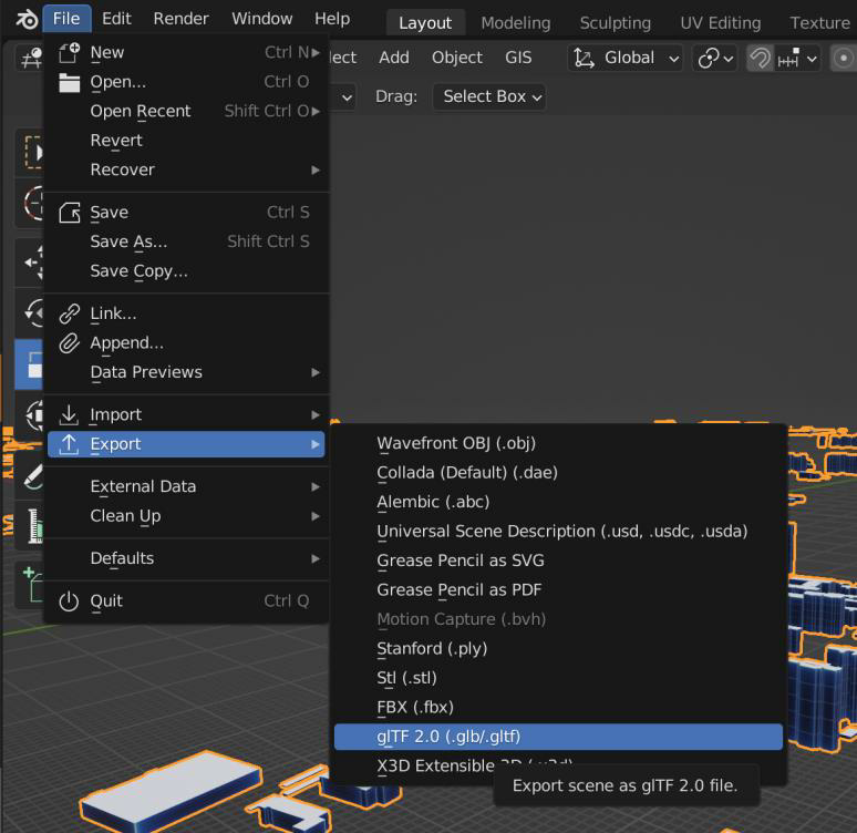
i. 【File】-【Export】-【glTF 2.0 (.glb/.gltf)】
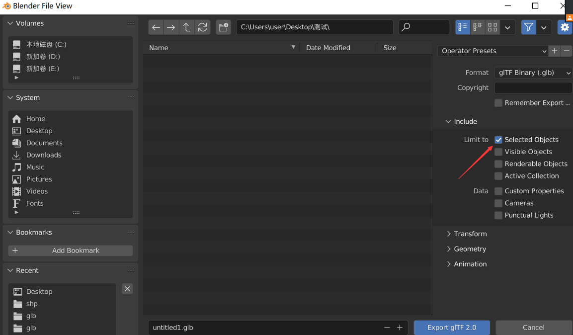
ii. Check if only selected layers will be exported【Selected Objects】
7、Multiple data processing
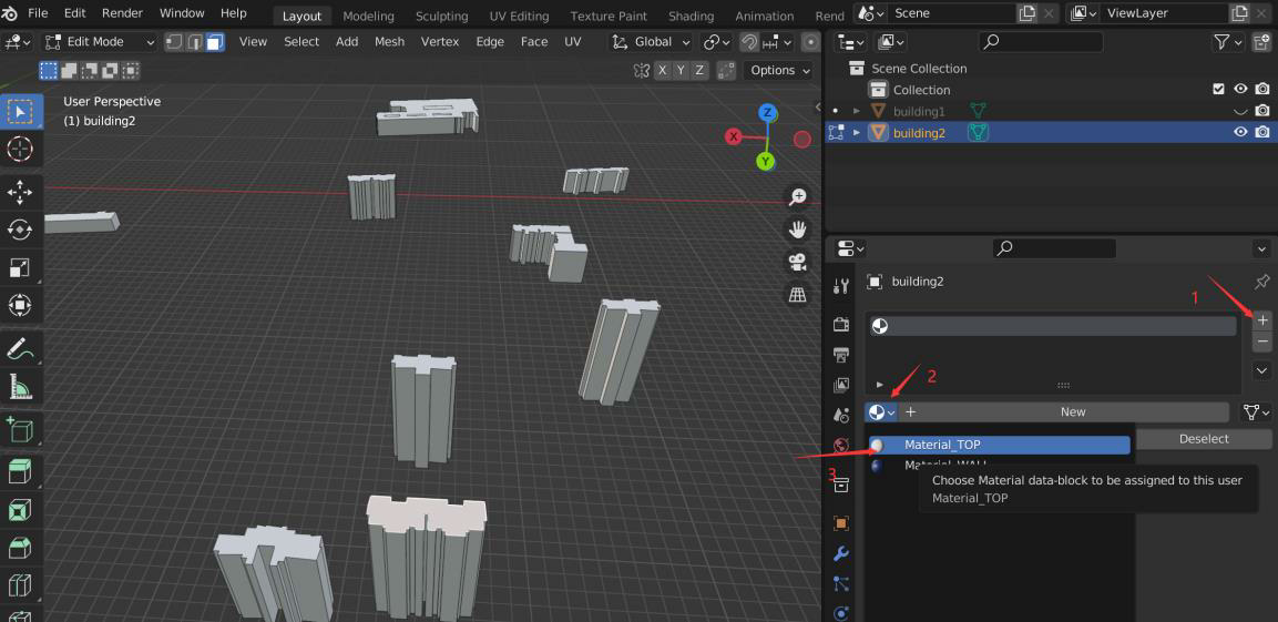
If there is more than one data, add process repeat steps1-6,When creating a material, reuse the previously created material. The operation is as follows:
8、View at origin
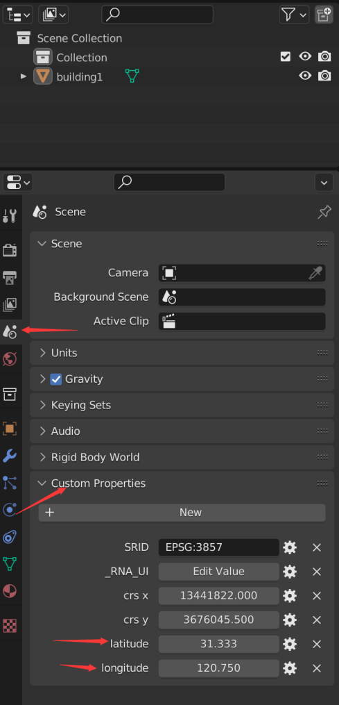
When providing it to the front end, you need to know the center point of the model, click【Scene Properties】 -【Custom Properties】,Check"longitude"and"latitude"value.