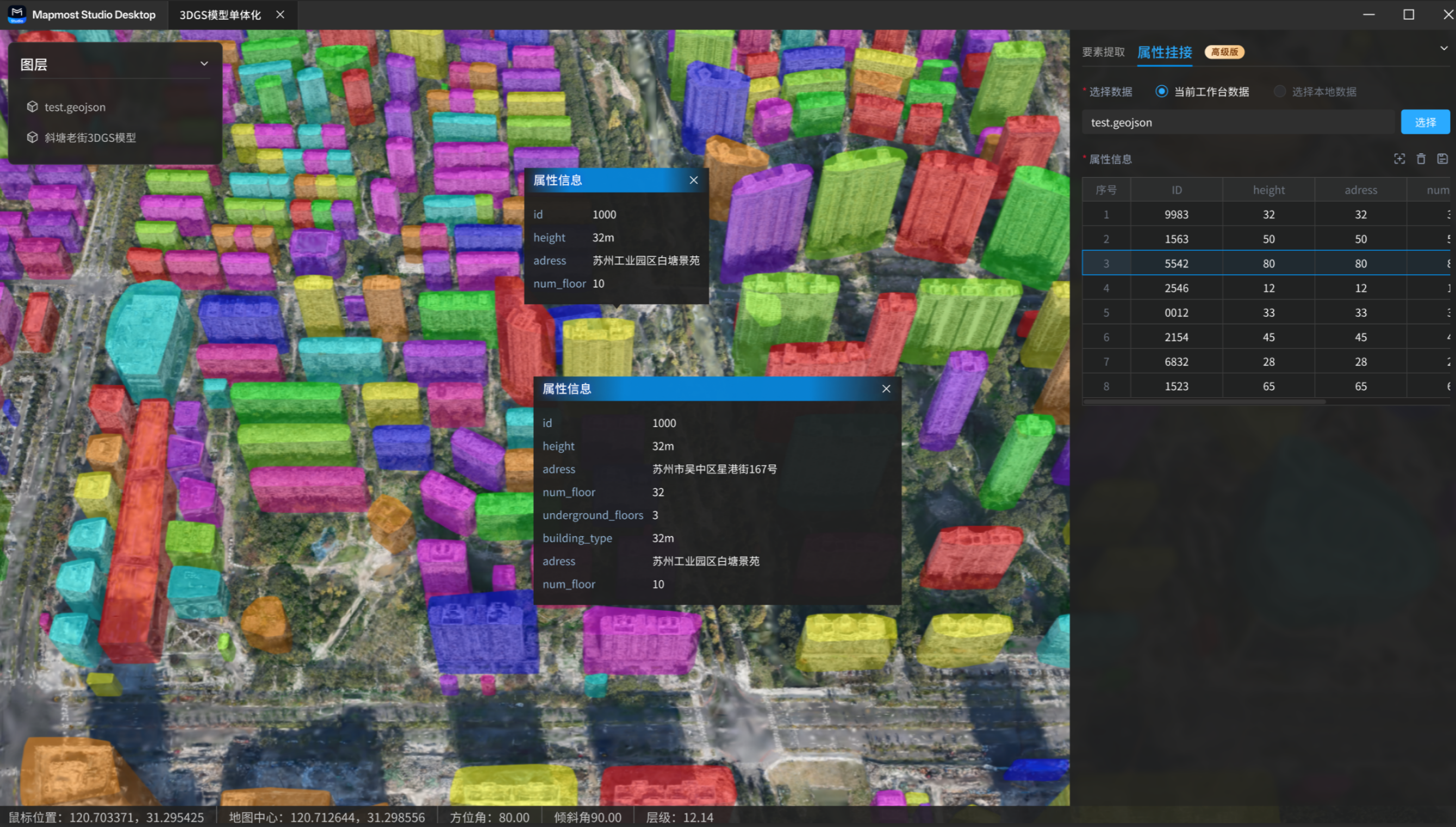
3DGS Instance Segmentation
The 3DGS instance segmentation feature extracts building features from 3DGS models, converts them into individual objects, and lets you edit and view business attributes for the extracted results. The final output is a GeoJSON file that can be loaded in Mapmost SDK for WebGL to build industry-grade digital twin applications.
This is an Advanced feature. It is available as a free 7-day trial. To renew or purchase it, contact customer service.
1. Feature Entry
On the Mapmost Studio Desktop home page, click 3DGS Instance Segmentation in the left navigation bar to open the 3DGS instance segmentation page.
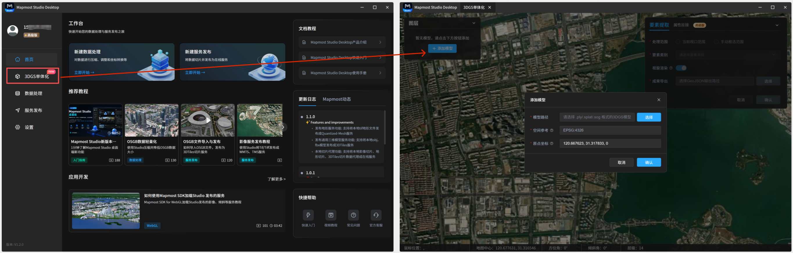
2. Add a 3DGS Model
When you open the 3DGS instance segmentation page, the system prompts you to add a 3DGS model. Select the model, enter the origin coordinates, and add the model to the scene.
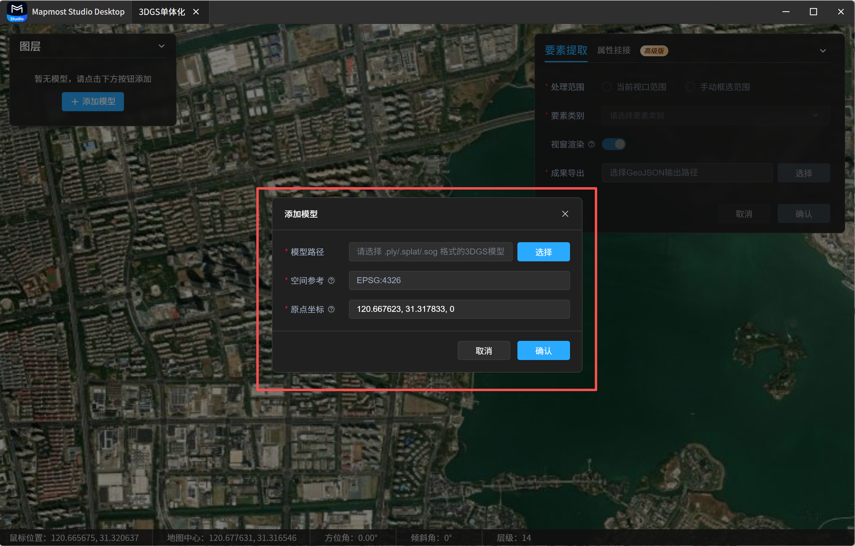
You can also close the add-model dialog and later click Add Model in the Layers panel in the upper-left corner of the 3DGS instance segmentation page.
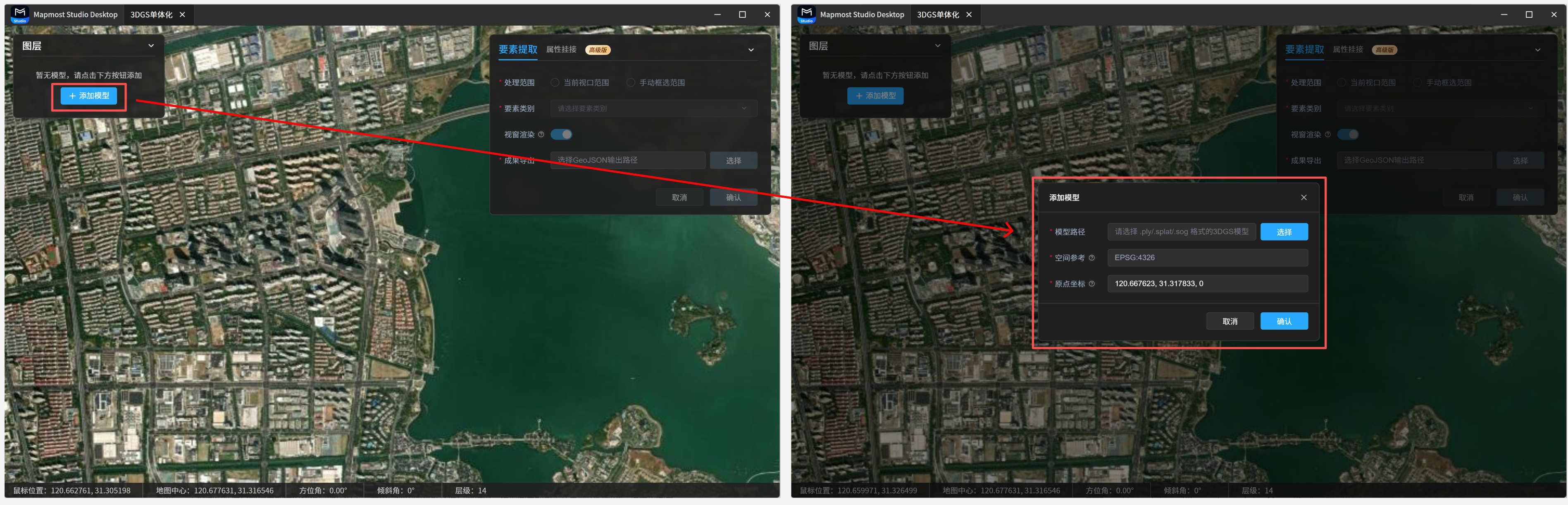
2.1 Add Steps
- Select a local 3DGS model file. Supported file formats are
ply,splat, andsog. - Confirm the spatial reference. The current default is
EPSG:4326. - Enter the model origin coordinates, including longitude, latitude, and height. The default origin coordinate is
(120.667623,31.317833,0). Use the origin coordinates output by your modeling software. For example, when modeling with the Mapmost Studio 3DGS extension package, you can find the model origin coordinates in the model list. - Click OK. After the model is added, the system automatically locates the scene based on the origin coordinates. If the default origin is used, the model is placed near Suzhou Center and the scene automatically moves to that area.
2.2 Manage Model Layers
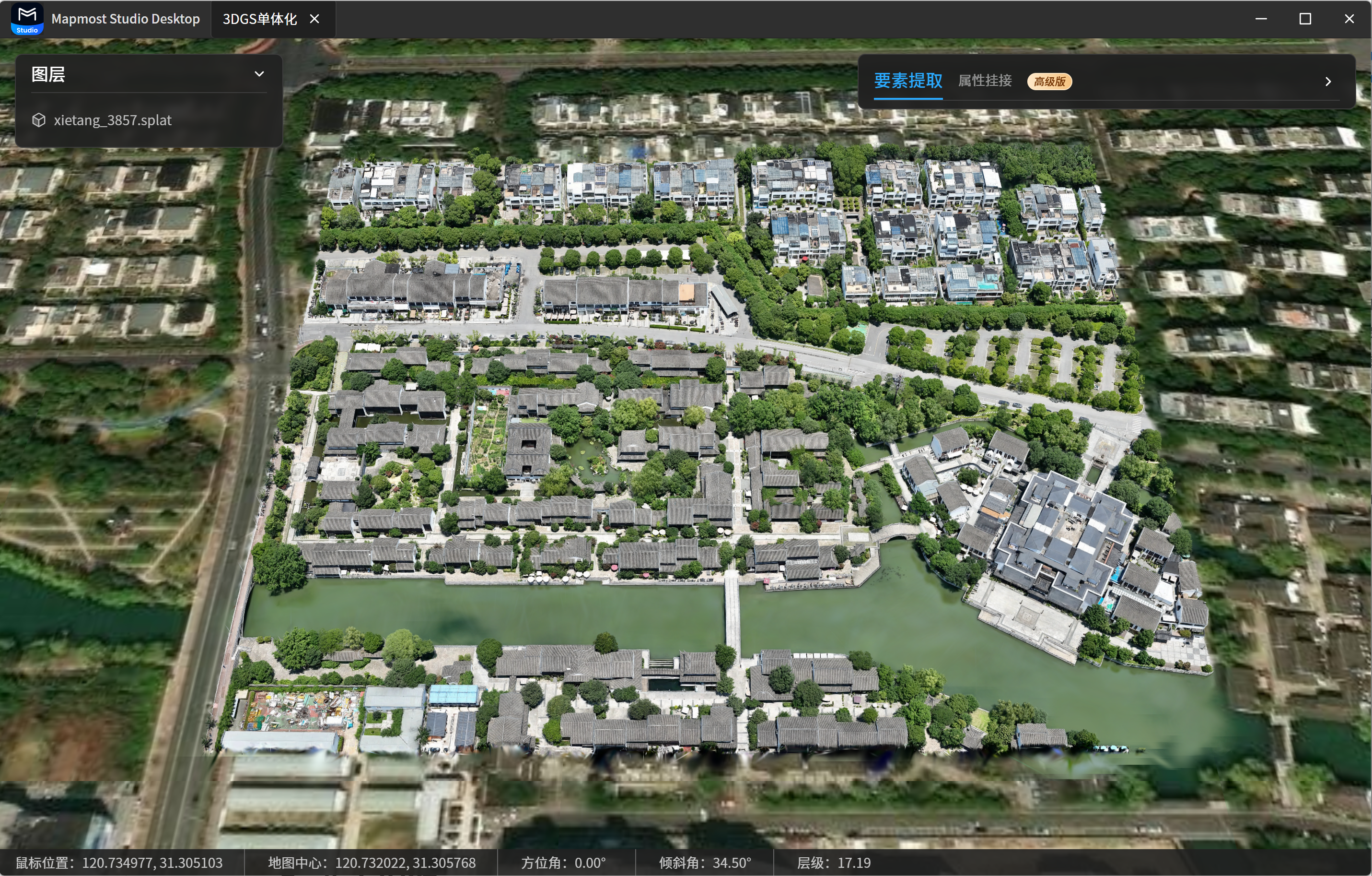
After a model is added, its name appears in the Layers panel in the upper-left corner. Hover over the model name to show the following actions:
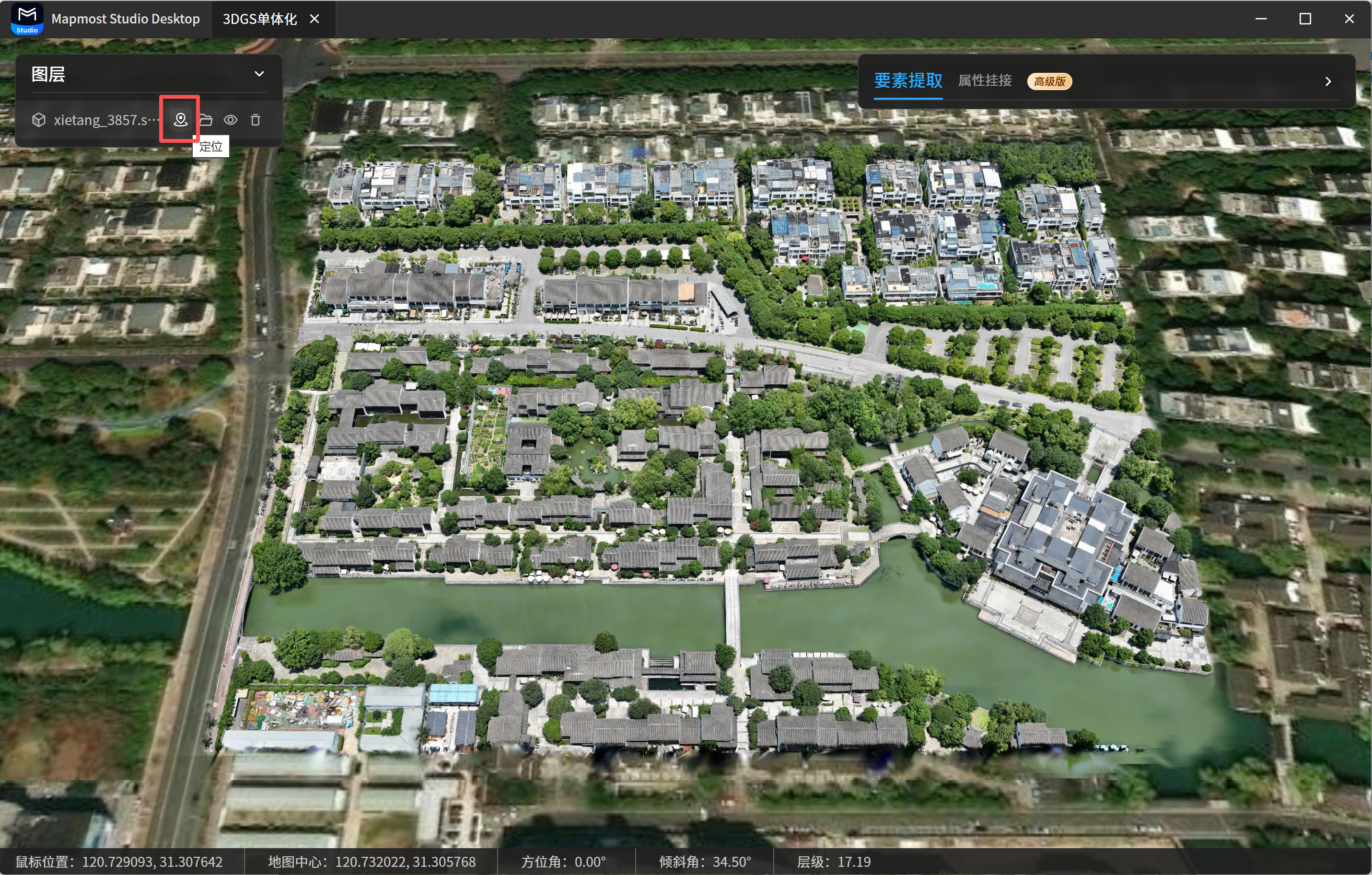
- Locate: click the locate icon to move the viewport to the model's default view.
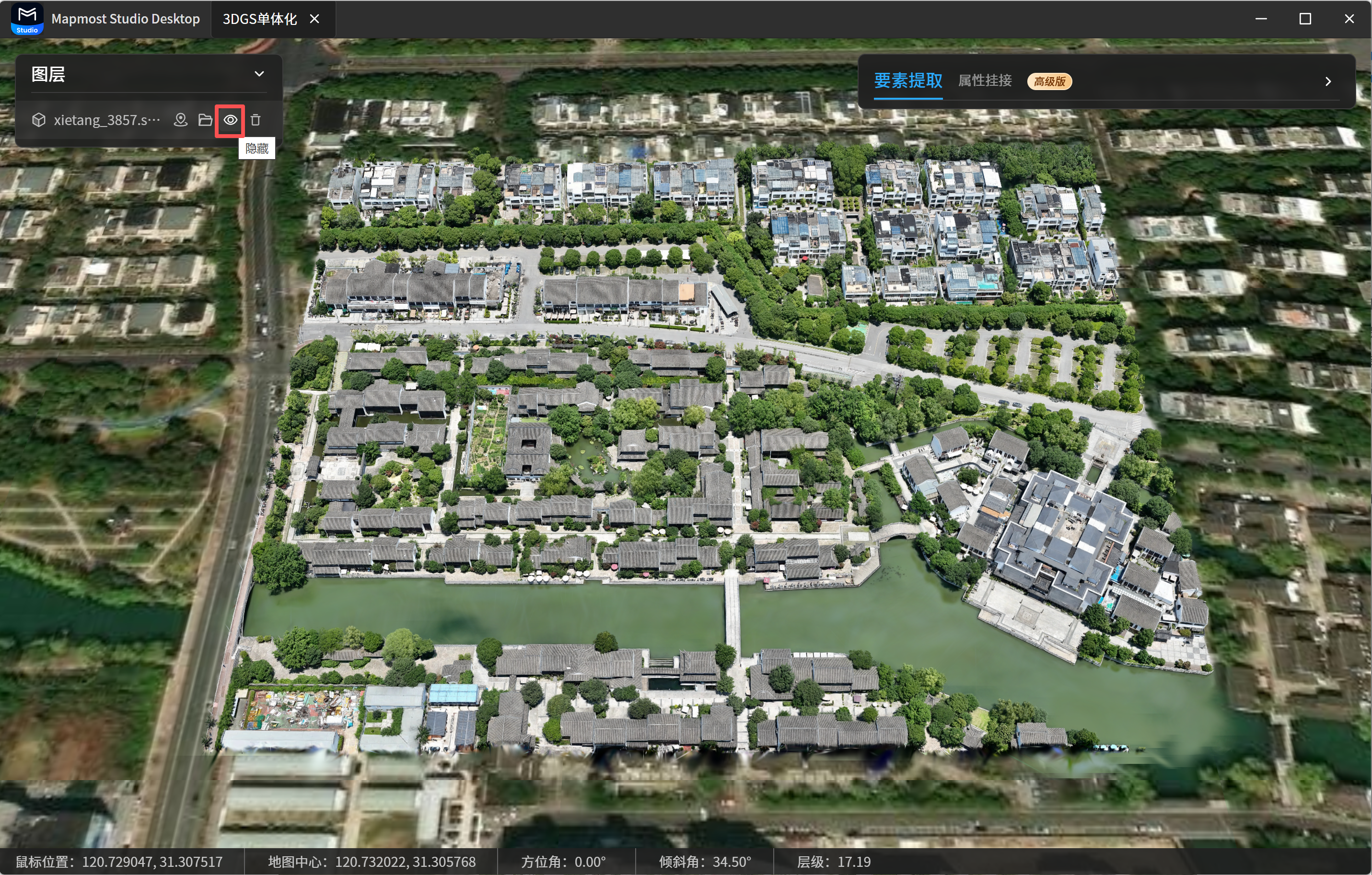
- Show/Hide: click the eye icon to show or hide the model.
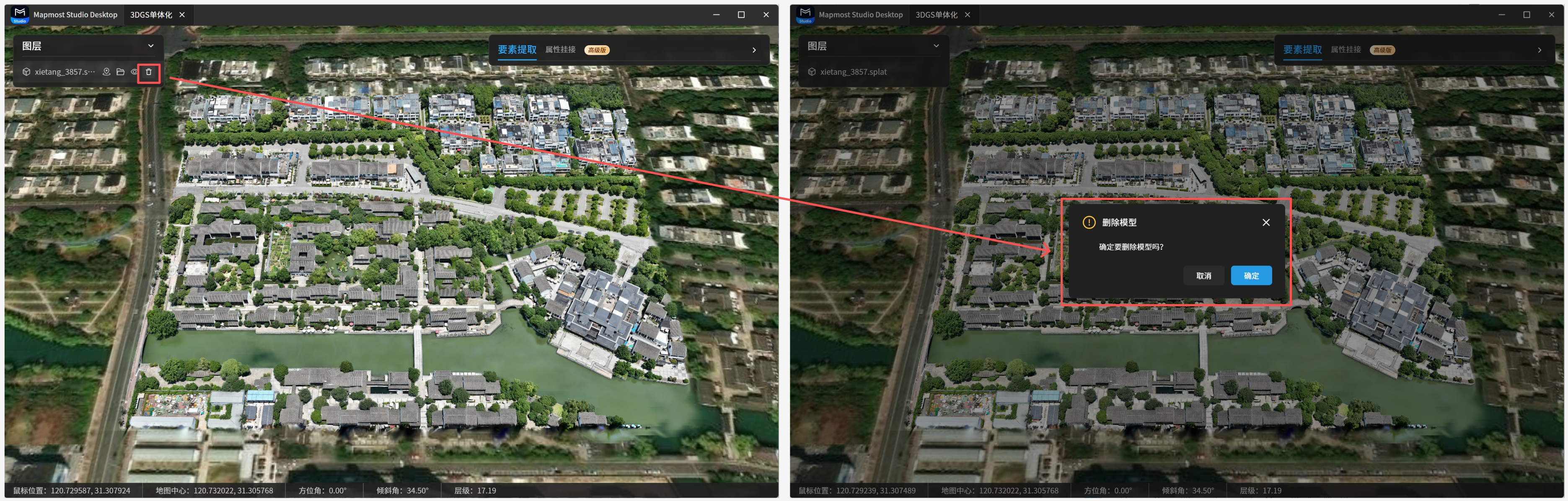
- Delete: click the delete icon to delete an added model. A model that is being processed cannot be deleted. The system asks for confirmation before deletion.
3. Feature Extraction
Feature extraction extracts building footprints and heights from an added 3DGS model. Here, height means the elevation from the building roof surface to the ground plane. The current version only supports the Building type. Other feature types, such as roads, vehicles, and streetlights, will be supported later.
After opening the 3DGS instance segmentation page and adding a model, switch to Feature Extraction in the right panel. Complete the processing range, feature type, viewport rendering, and result export settings.
3.1 Parameter Settings
3.1.1 Select Processing Range
The processing range determines which model area is used for feature extraction. Two methods are supported:
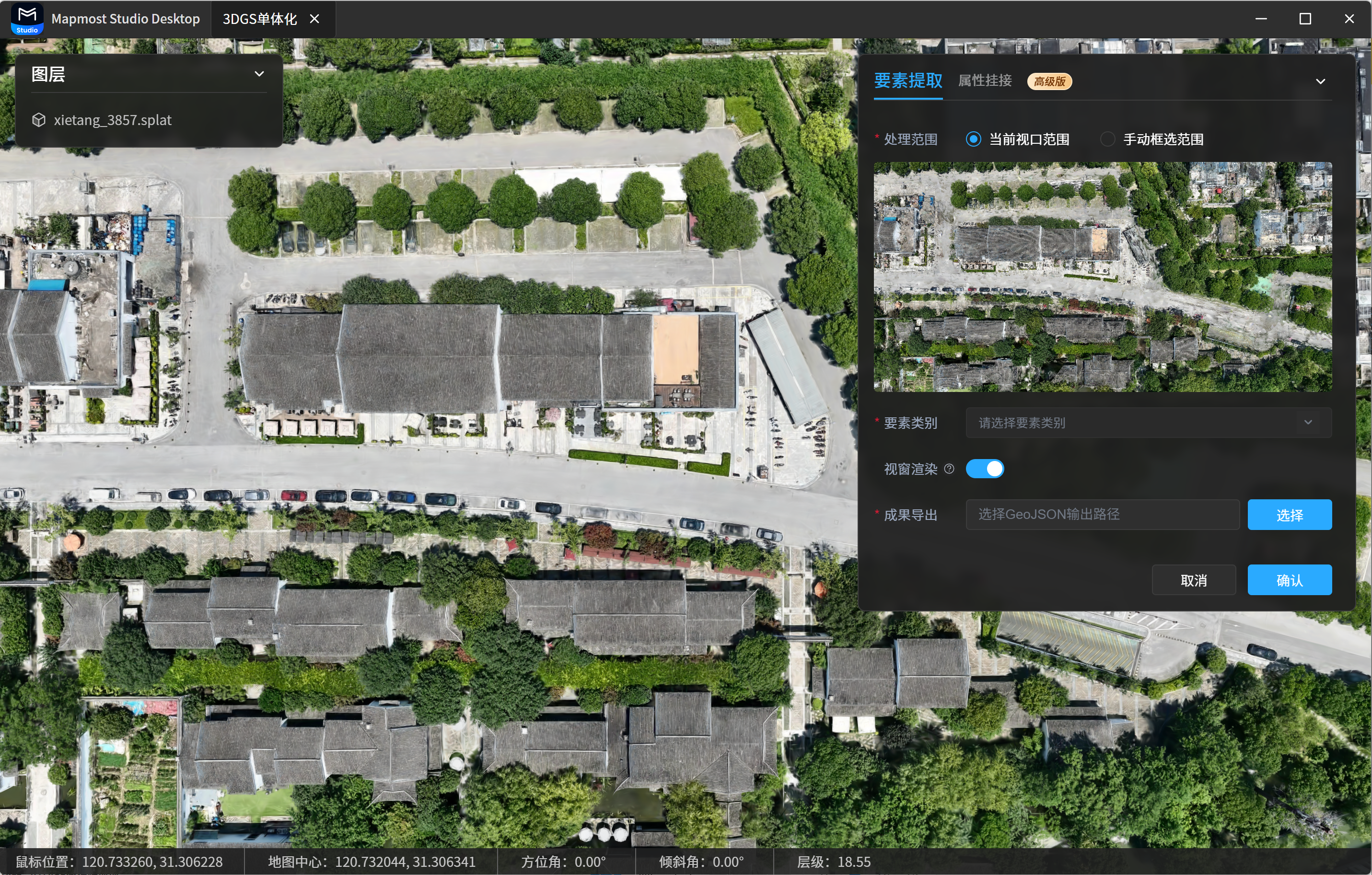
- Current Viewport Range: the system displays the rendered model image in the current viewport. Feature extraction is performed only within this range.
- Manual Selection Range: draw a rectangular area in the viewport. After the selection is complete, the system displays the rendered model image in the selected range and performs feature extraction within that range.
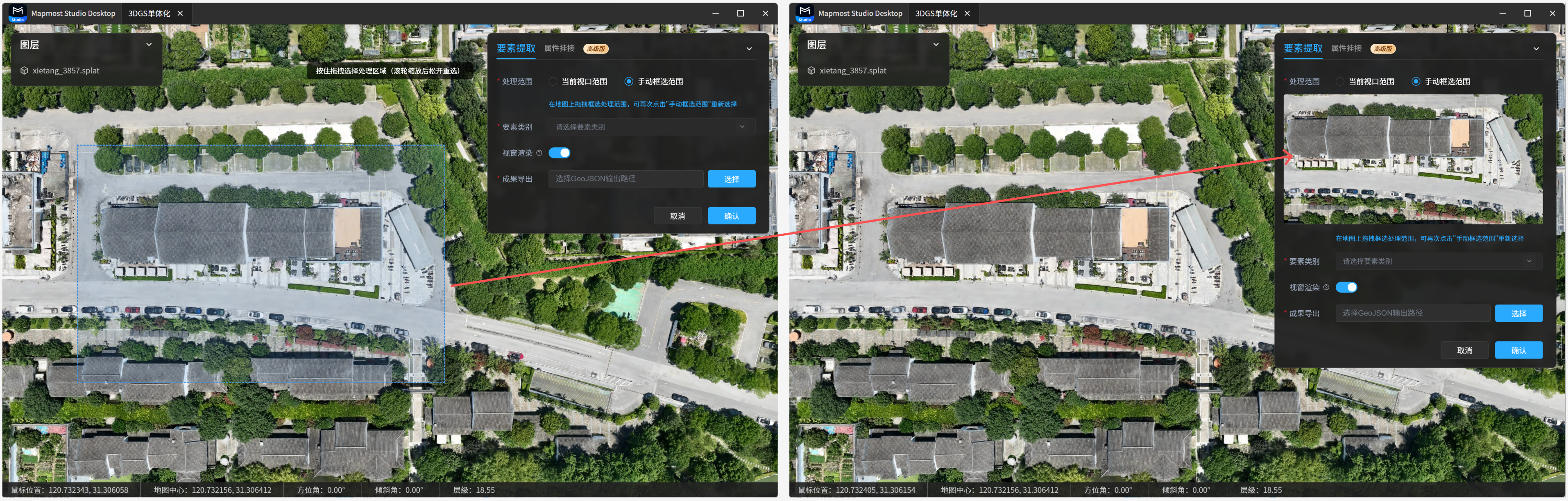
After either range is selected, the model in the viewport switches to a top-down view so you can confirm the extraction area.
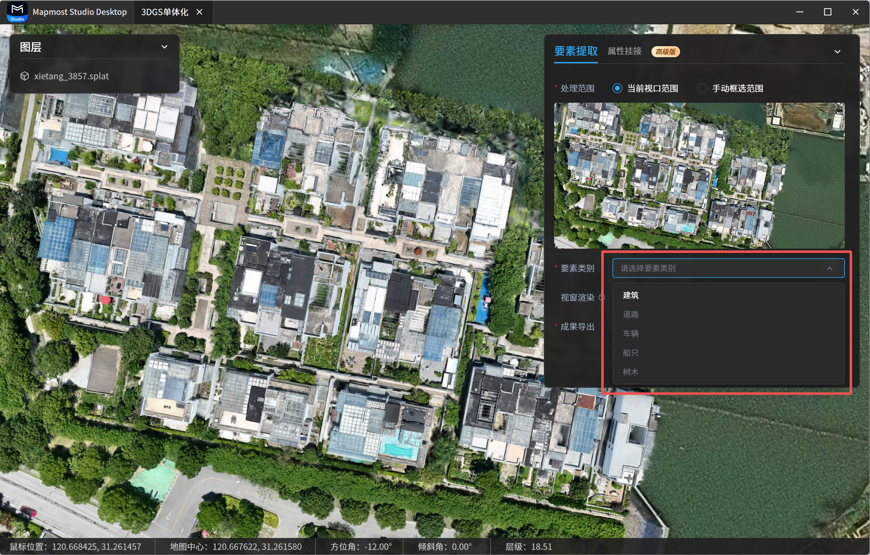
3.1.2 Select Feature Category
The current version only supports Building. Other types are disabled and cannot be selected.
3.1.3 Configure Viewport Rendering
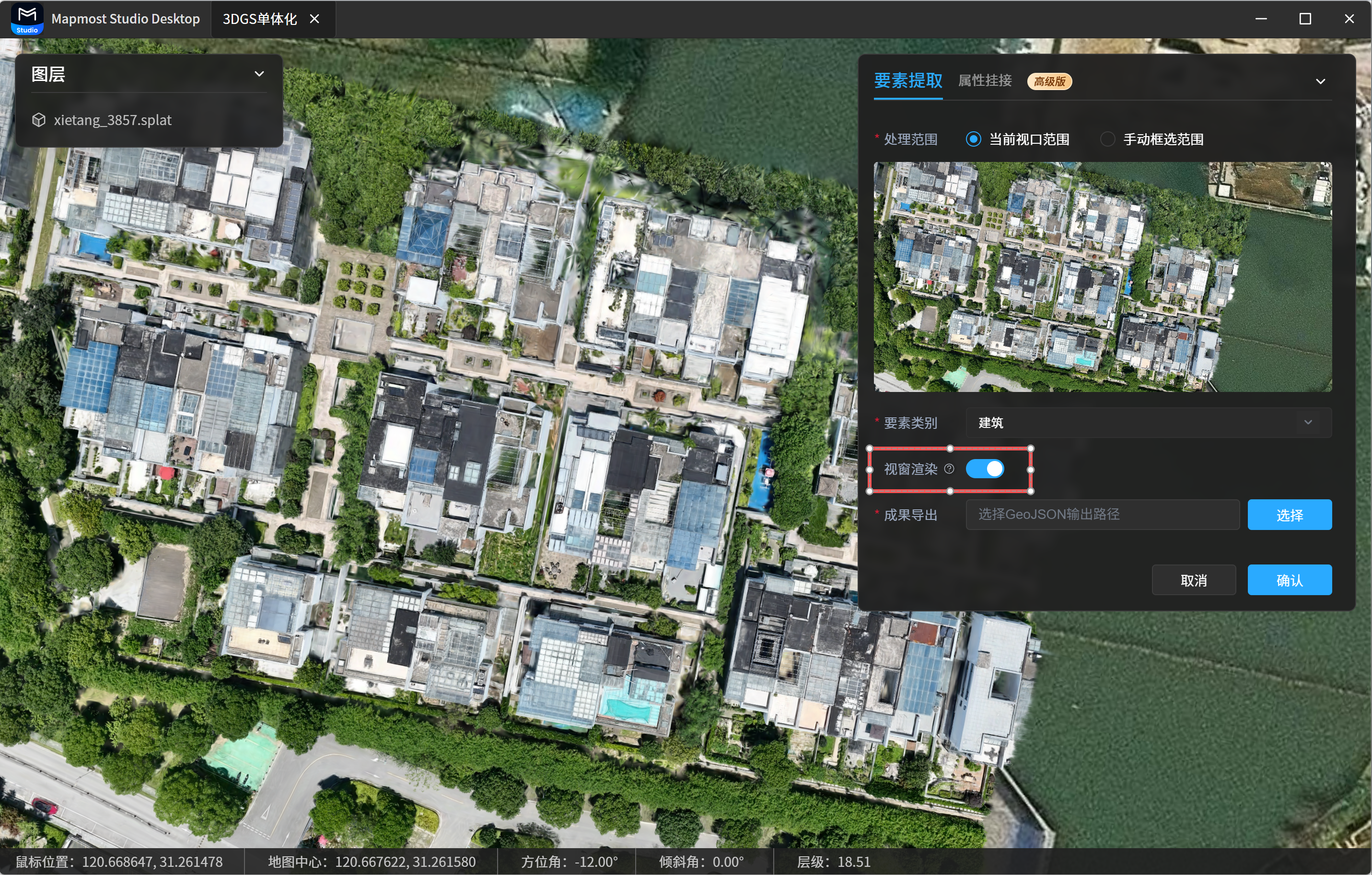
When Viewport Rendering is enabled, processed feature results are automatically overlaid in the current viewport so you can check the extraction result immediately. When it is disabled, the system only generates the result file and does not overlay the result in the viewport. Enabling this option is recommended.
3.1.4 Configure Result Export
Feature extraction results are exported as a GeoJSON file.
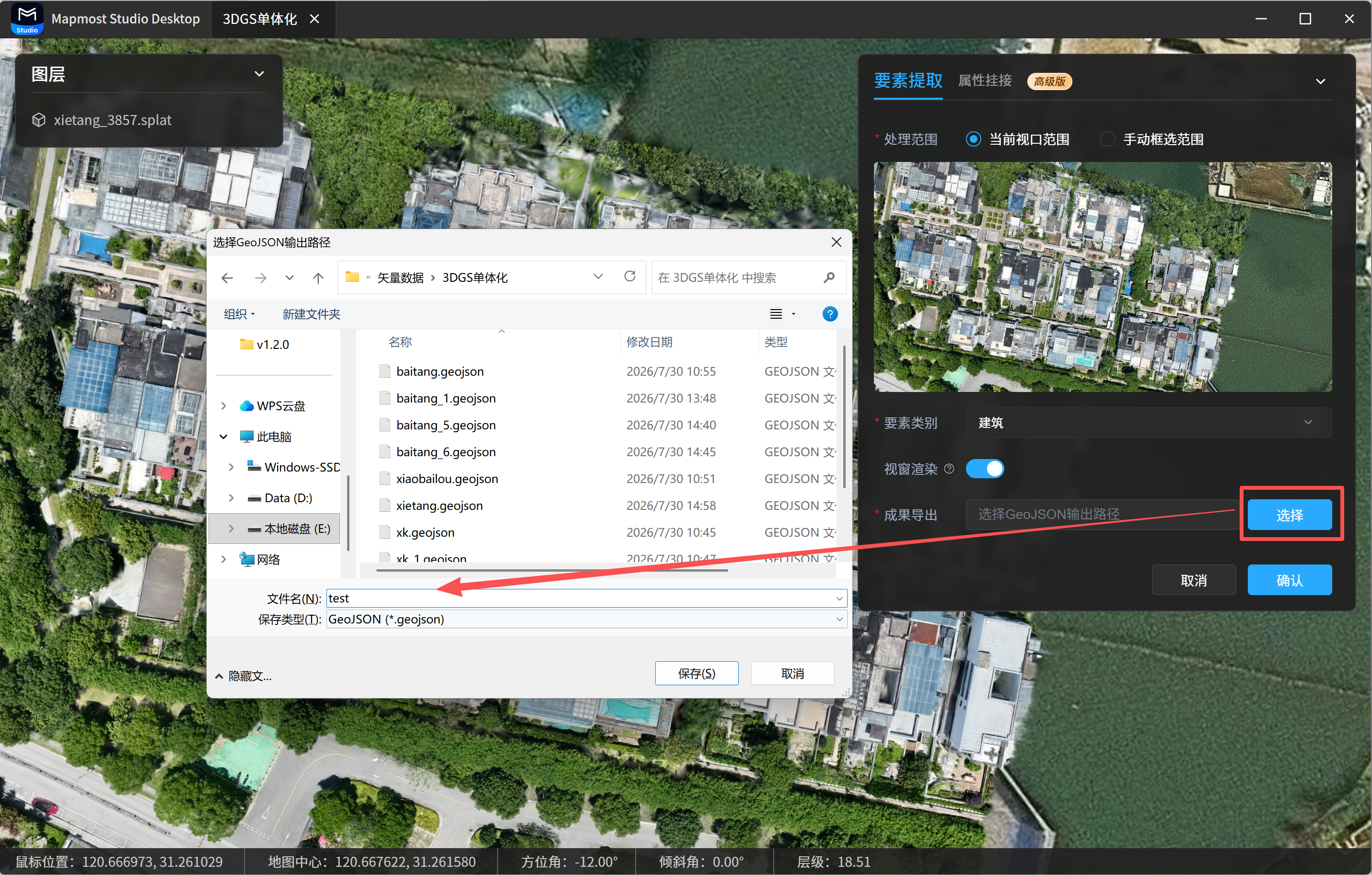
- In Result Export, click Select.
- Choose a local save path and enter the GeoJSON file name.
- Click OK to start processing.
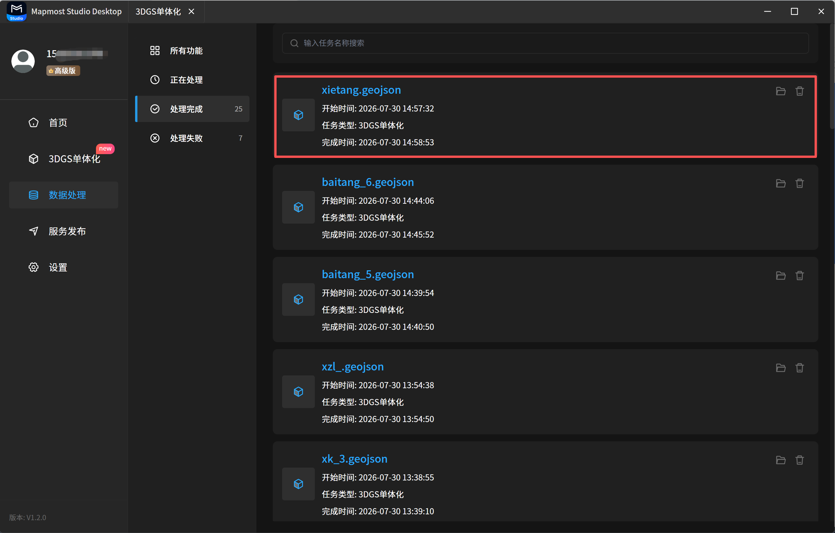
After you click OK, the system adds a processing record under Data Processing - Processing/Completed. The record name is the GeoJSON file name you set.
3.2 Task Management
3.2.1 Task Status
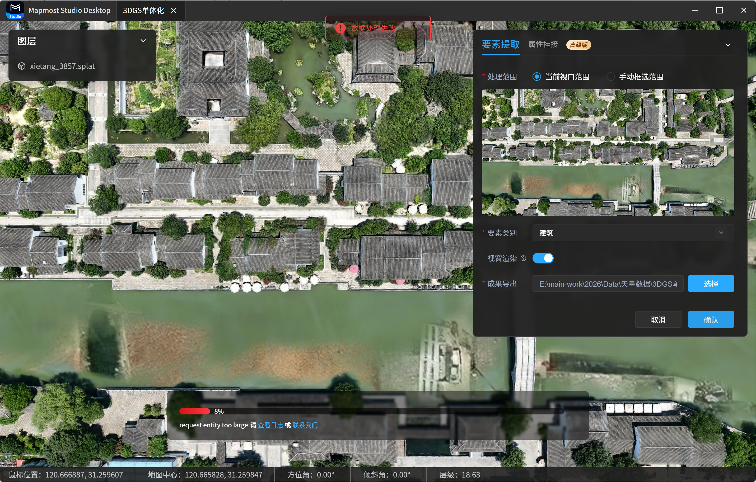
3DGS instance segmentation task statuses include Processing, Completed, and Failed. Failed tasks show a red progress bar on the 3DGS instance segmentation page and display the failure reason. You can view logs or contact customer service for help.
3.2.2 View Tasks
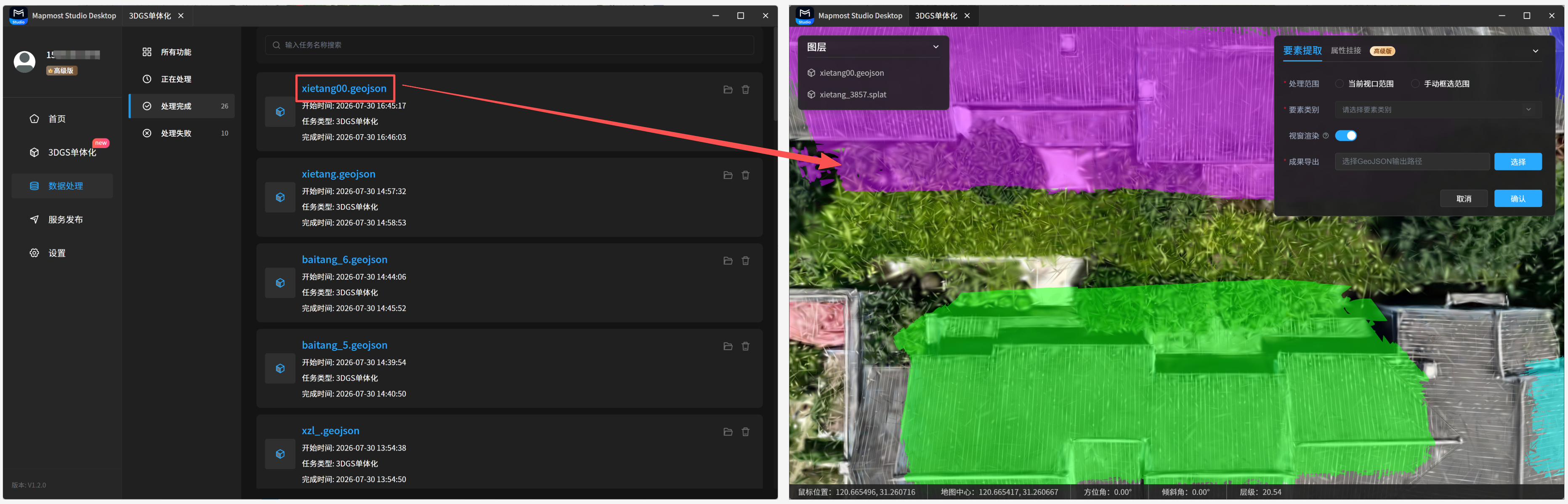
Processing instance segmentation tasks can be viewed in Data Processing - Processing. Click a task to open the 3DGS instance segmentation page. Completed tasks can be viewed in Data Processing - Completed. Click a task to open the 3DGS instance segmentation page.
3.2.3 Closing a Running Task
If a 3DGS instance segmentation process is running and you close the page, the system displays a prompt:
- Select Close Anyway to close the page and end the current process.
- Select Cancel to keep the current page open and keep the process running.
Notes during processing:
- All model operations are disabled during 3DGS feature extraction.
- If you exit the software, lose network connection, or return to another page after processing starts, the started process continues to run.
- If processing has not started, 3DGS instance segmentation cannot be used while offline.
- When you click Mapmost Studio Desktop in the upper-left corner, the app returns to the home page if you entered from the home page, or to the data processing page if you entered from the data processing module.
4. Attribute Attachment
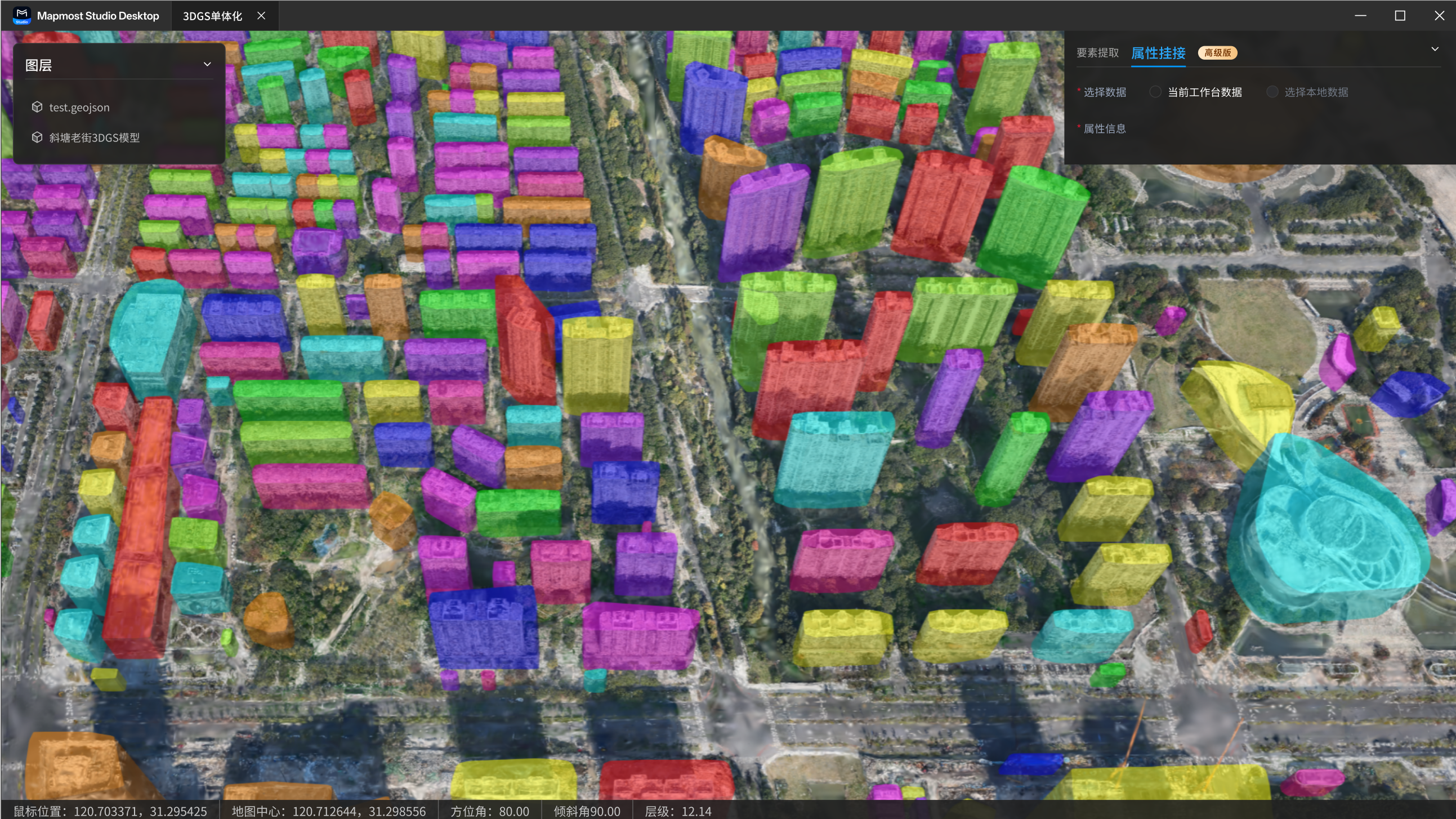
Attribute attachment is used to edit attributes for feature extraction results. If Viewport Rendering was enabled during feature extraction, the extraction result is displayed directly in the scene, and the corresponding GeoJSON file appears in the Layers panel in the upper-left corner.
4.1 Select Data
In the Attribute Attachment panel, select the GeoJSON data to edit. The current version only supports Current Workspace Data. Select Local Data is not yet supported.
- If there is only one GeoJSON dataset in the current workspace, it can be selected directly.
- If there are multiple GeoJSON datasets in the current workspace, select one from the drop-down list.
4.2 Edit Attribute Information
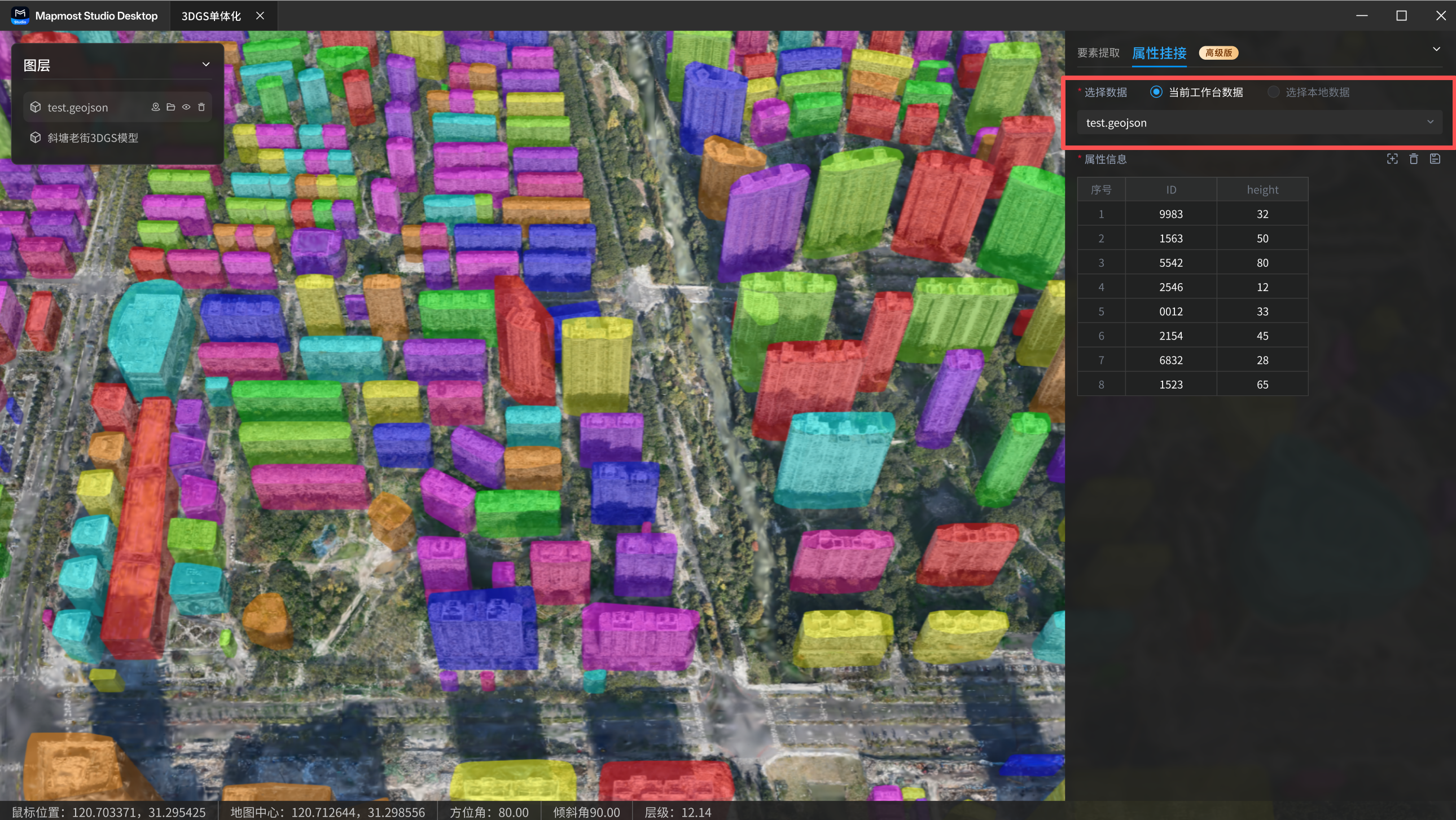
After data is selected, the attribute information table displays all feature data in the GeoJSON file:
- Each row in the table represents one feature.
- Each column in the table represents one attribute field.
- Default fields include
idandheight.
4.2.1 Create a Field
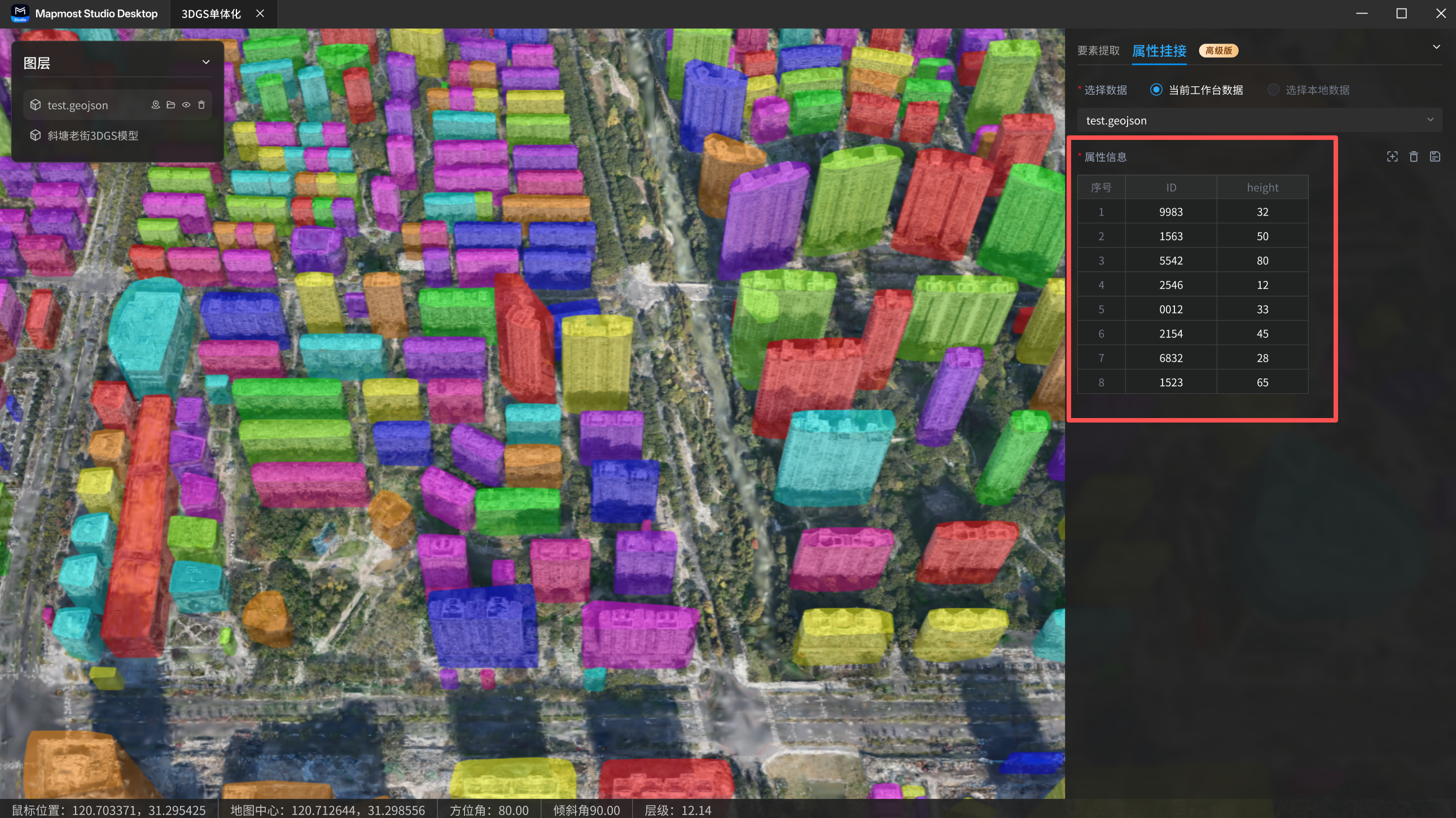
Click Create Field to open the Create Field dialog. Enter the field name, field type, and related parameters, then click OK.
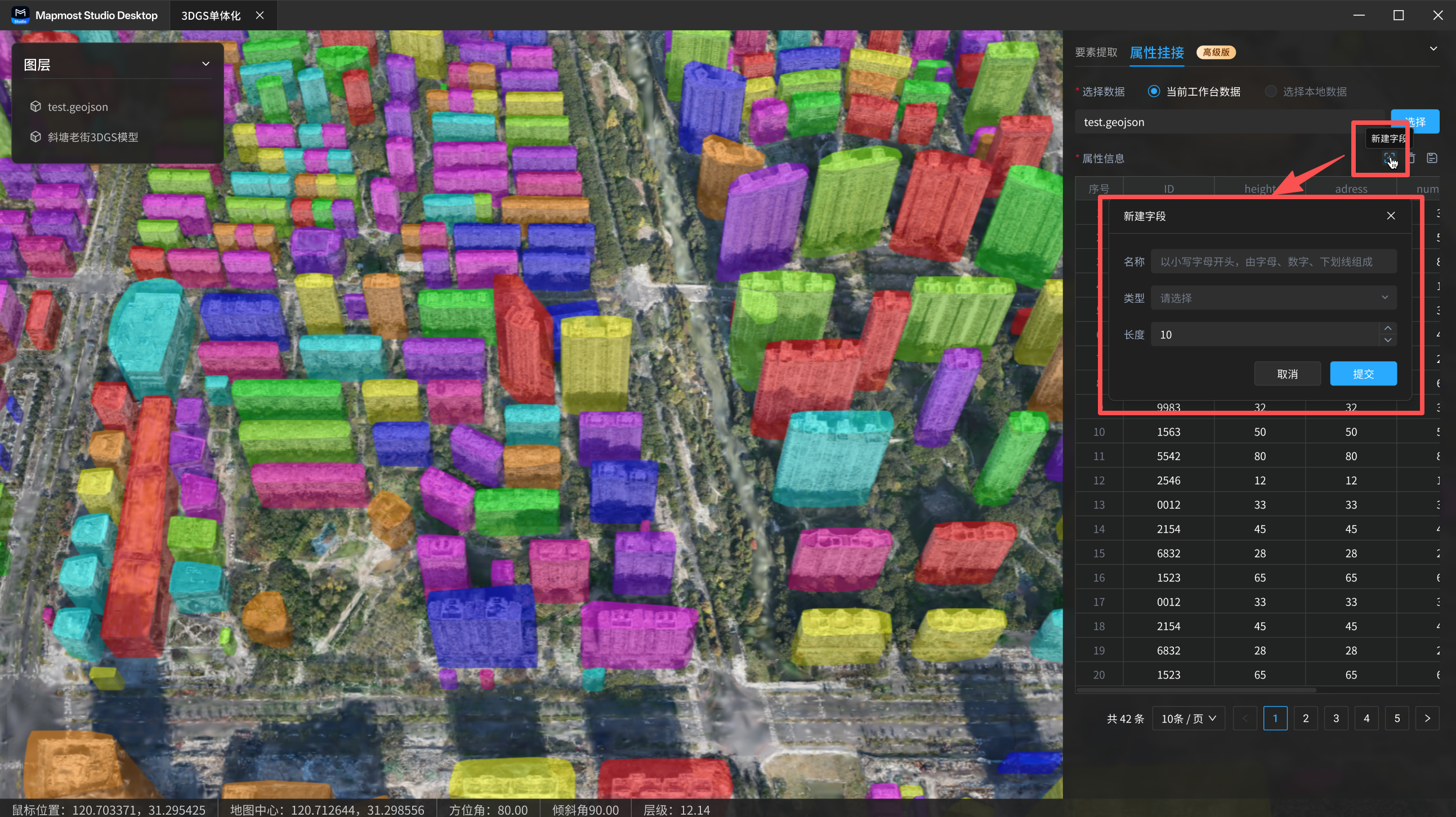
The field name must meet these rules:
- It must start with a lowercase letter.
- It must contain 4 to 32 characters.
- Only letters, numbers, and underscores are supported.
Field type and parameter rules:
- Integer (32-bit): enter the length.
- Integer (64-bit): enter the length.
- Text (string): enter the length.
- Single-precision floating point (float): enter the length and precision.
- Double-precision floating point (double): enter the length and precision.
Precision indicates the number of digits retained after the decimal point.
4.2.2 Edit a Field
All fields except id can be edited.
Hover over a field name and click the edit icon to open the Edit Field dialog. You can change the field name, type, length, and related information. Click OK when finished.
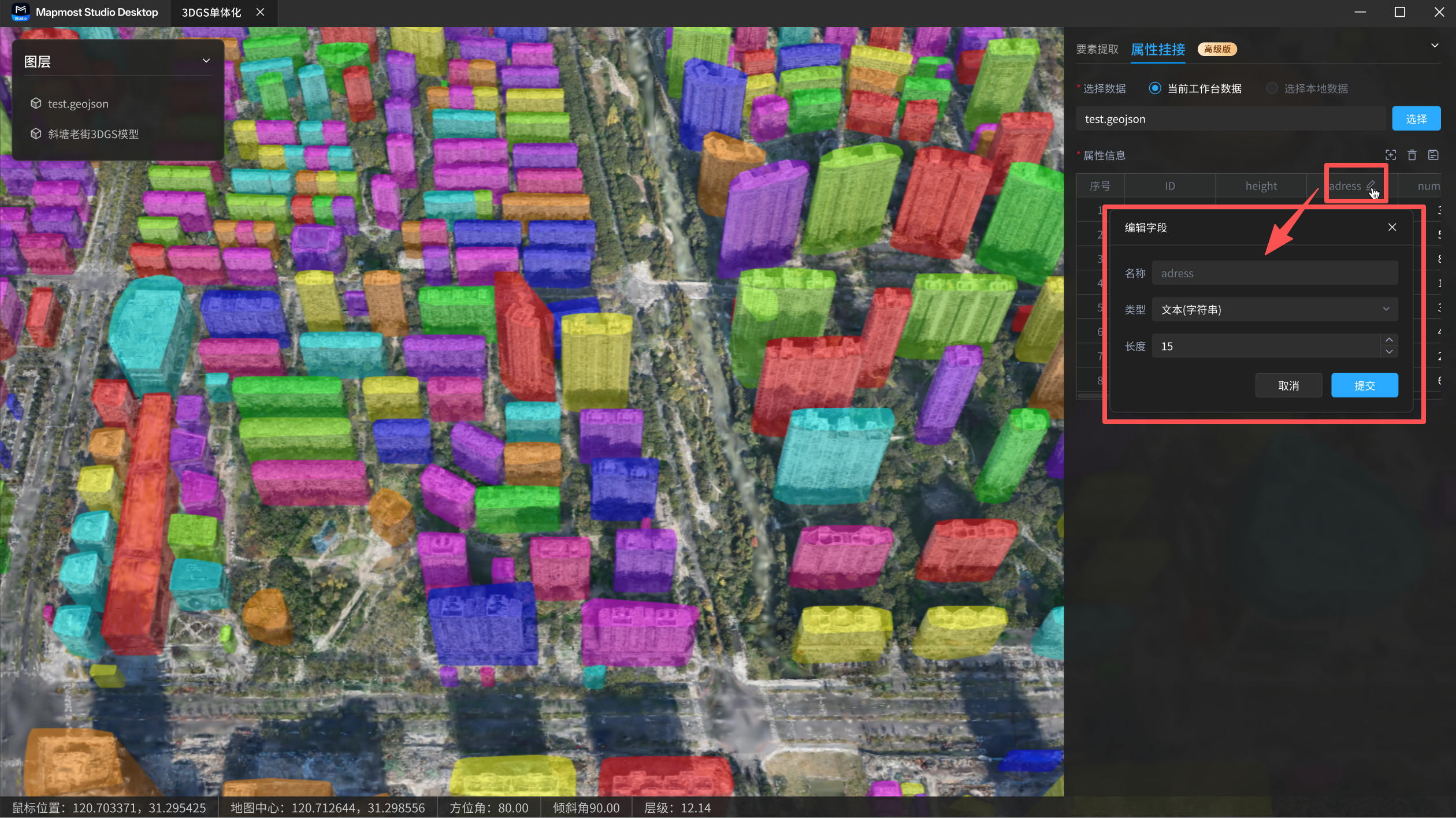
Field values can be edited directly. Double-click a cell to enter or delete a field value.
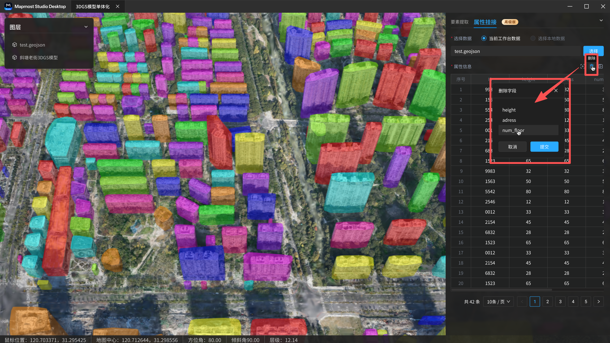
4.2.3 Delete a Field
All fields except id can be deleted.
Click the delete button, select the field to delete, and confirm according to the prompt.
4.3 View Attribute Information
After editing attributes, you can view feature attributes in the following ways:
- Click a row in the attribute list. The system automatically locates the corresponding feature on the map and displays its attributes in a popup.
- Click a feature directly on the map. The system displays the feature's attribute popup.