Icon point layer configuration
- Icon point layer is used to display the density or location information of point data and supports the function of adding icons. For details, please refer to "Background layer Background:1.2";
- Add the data source. If the data source already exists, ignore this step. For details, refer to "Cartography Prerequisite: 2";
- The "∑" button behind the parameter value can realize numerical changes at different levels. For details, please refer to "Icon Point Layer Symbol: 3.3.2";
- The "fx" button behind the parameter value can convert the parameter information into an expression. For details, refer to "Icon Point Layer Symbol: 3.3.3".
1. Layer Properties module
The "Layer Properties" module is used to adjust the layer data source, data type, display level, etc. For details, please refer to "Background layer Background: 1";
1.1 Set layer type
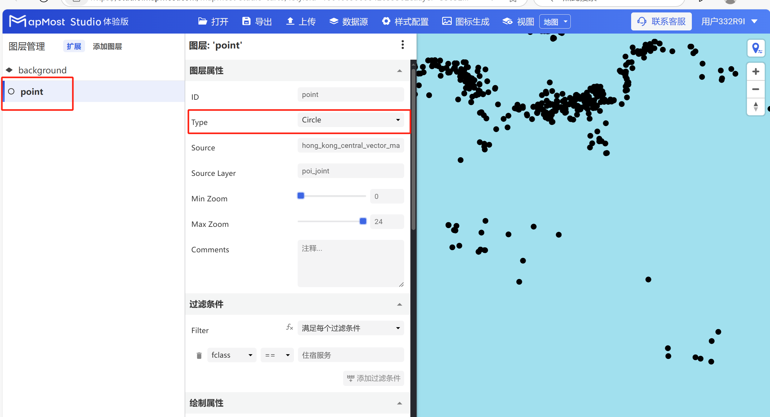
- Change "Type" to "Symbol", change "Source Layer", and set "Min Zoom" and "Max Zoom" (it is normal that no data is displayed in the layer viewport in the current state, and more parameters need to be further set before the data will be displayed);
2. "Filter conditions" module
- The "Filter Conditions" module supports filter condition selection and expression writing;
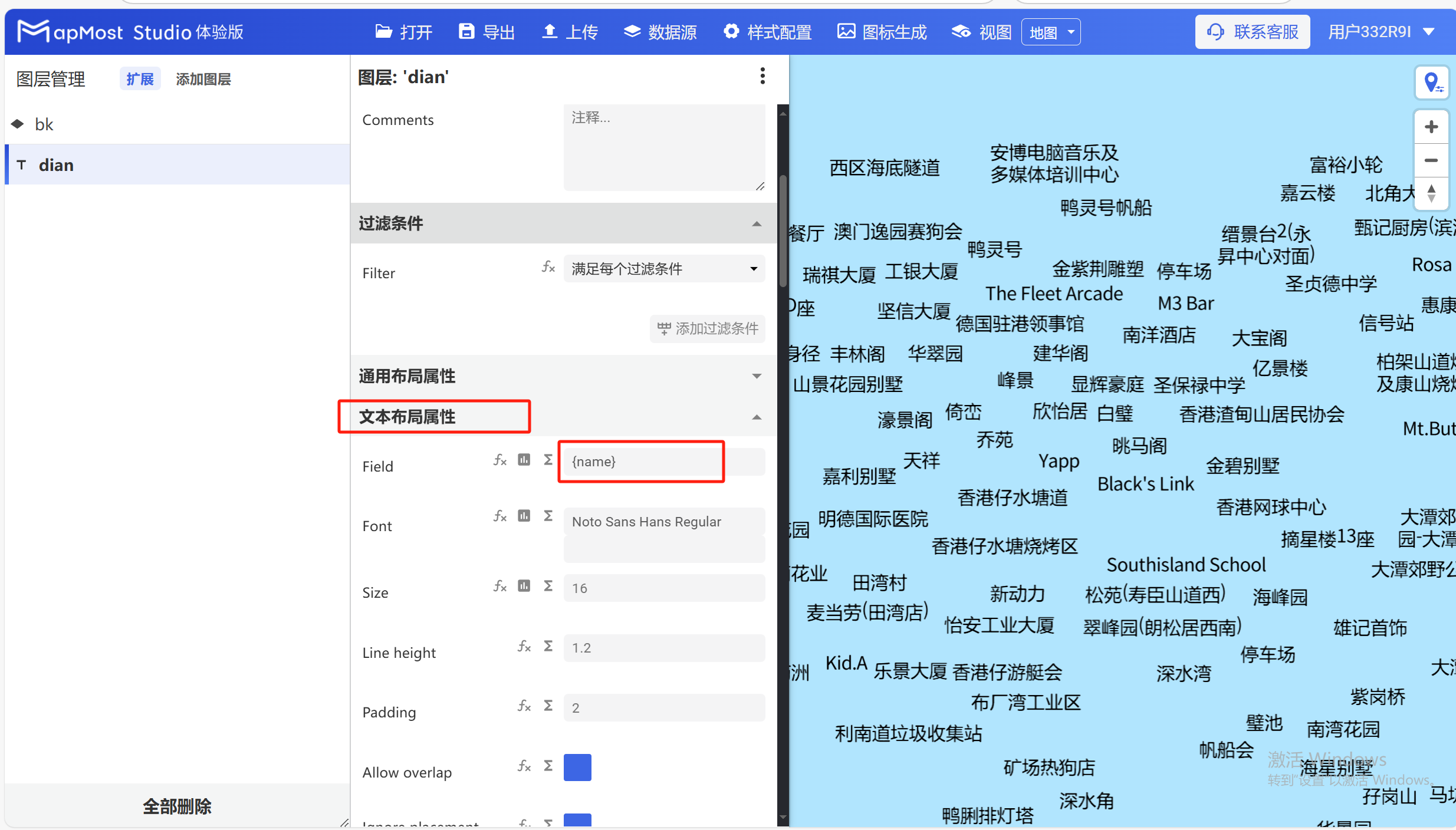
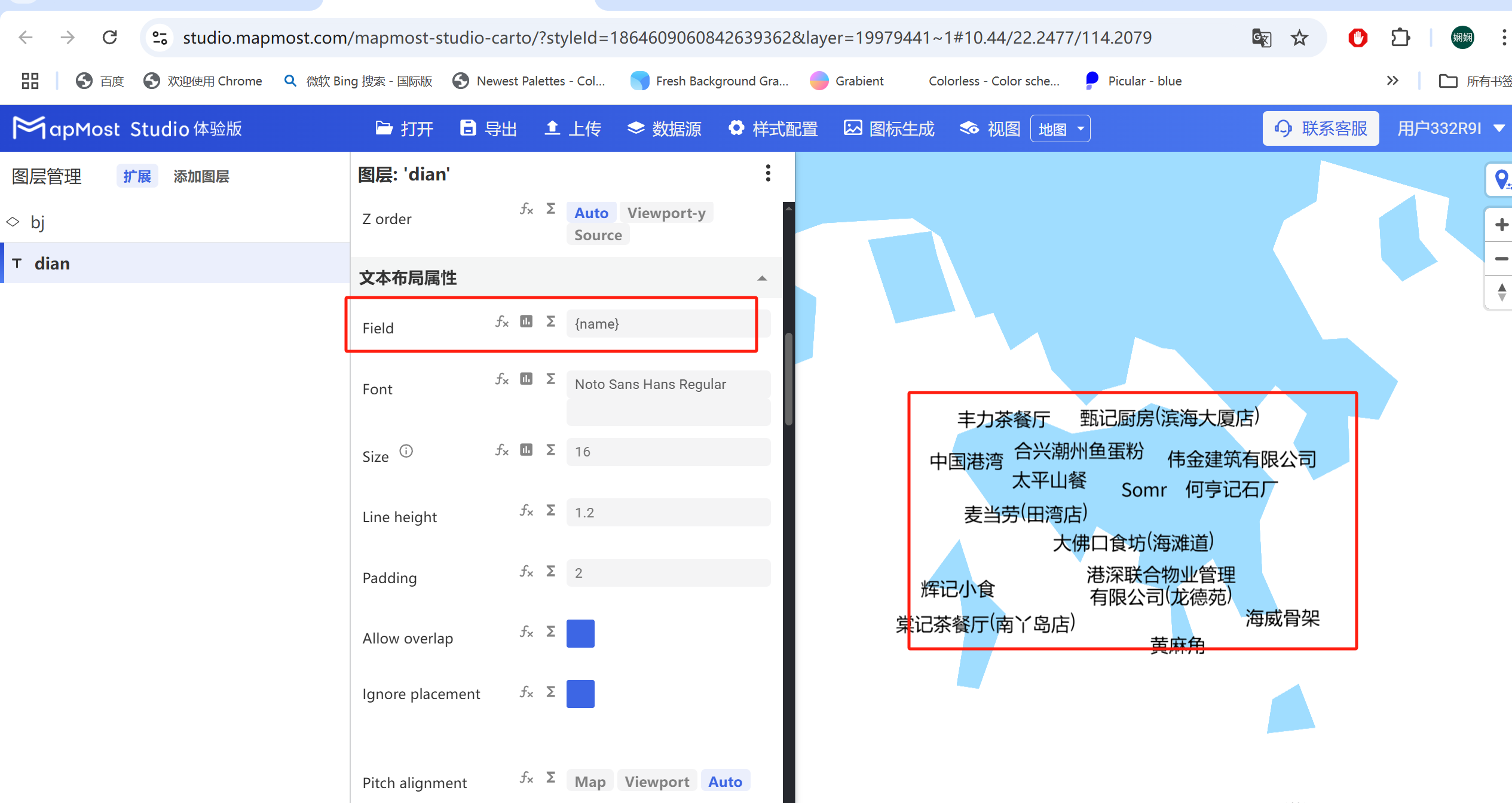
- In order to make the data visible, it is recommended to first call the name field of the data in the "Text Layout Properties". If this step is not set, the data will not be displayed in a normal state;
2.1. Set filter conditions
The "filter conditions" module can meet the different needs of simple filtering and complex filtering through the selection of "filter conditions" and the writing of expressions;
The initial interface is as follows:
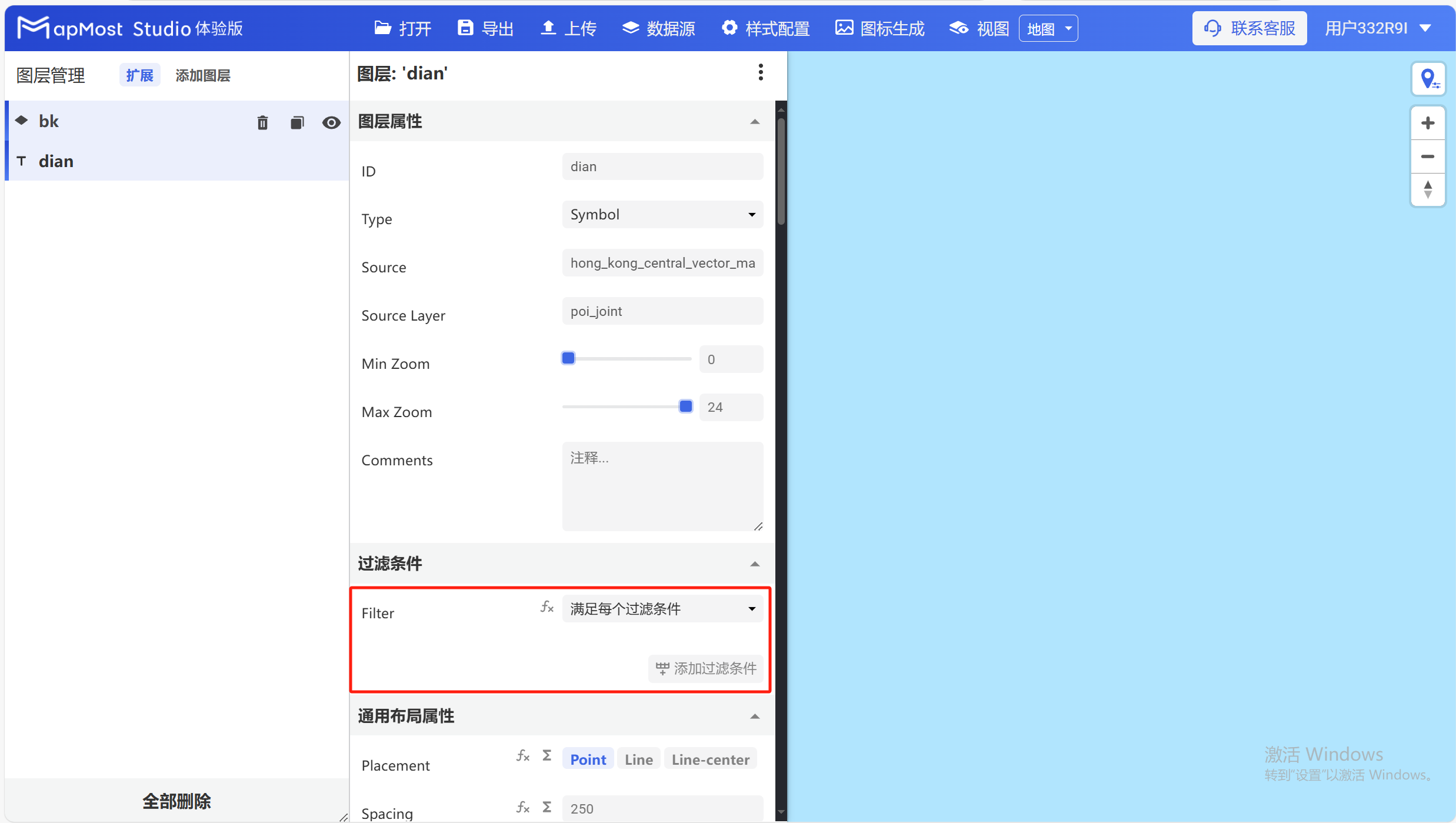
- In the drop-down selection box, you can select filtering requirements, including "meets every filter condition", "does not meet all filter conditions" and "satisfies any filter condition";
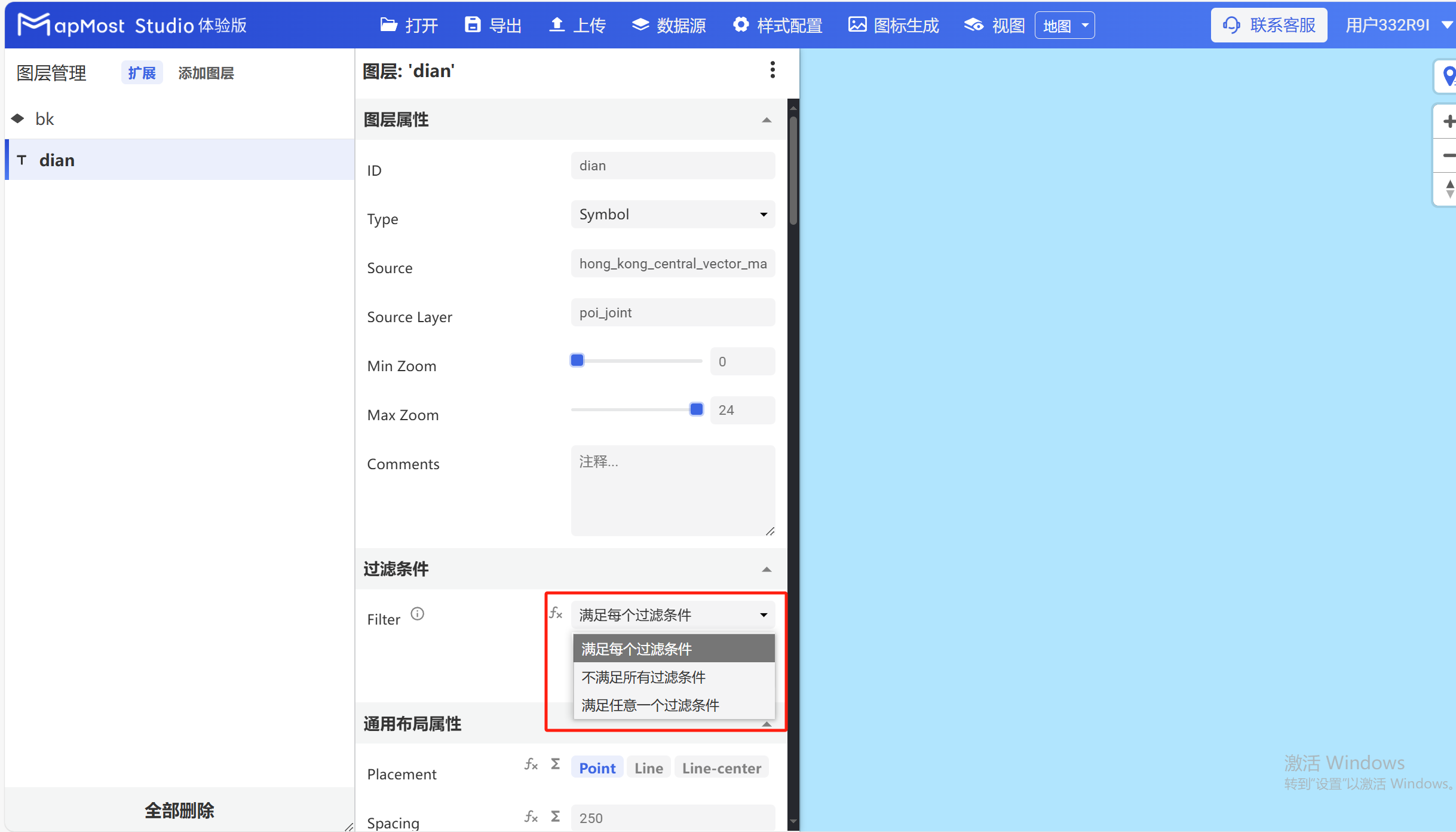
2.2. Add filter conditions
- Take selecting "Meet each filter condition" as an example, click the "Add filter condition" button, and the field filter input box will appear;
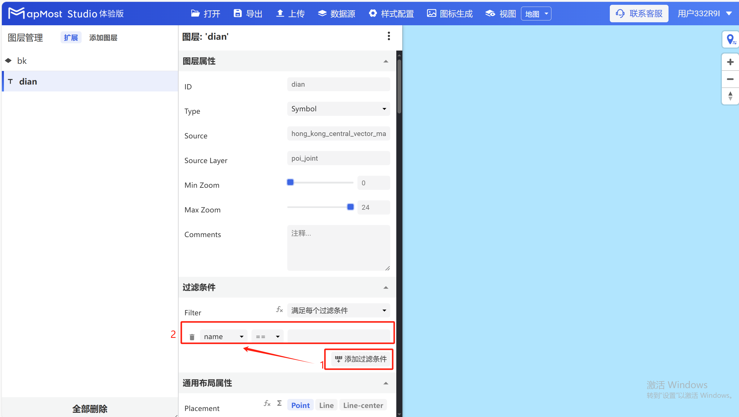
2.3. Select the filter field
- The fields selected when publishing the layer are displayed in the field selection box, and users can choose to filter the corresponding fields according to actual needs;
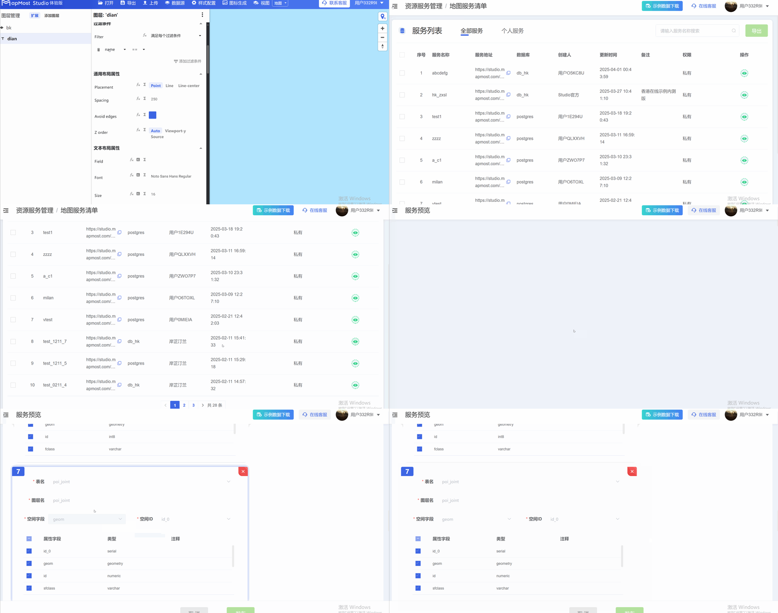
2.4. Select filtering method
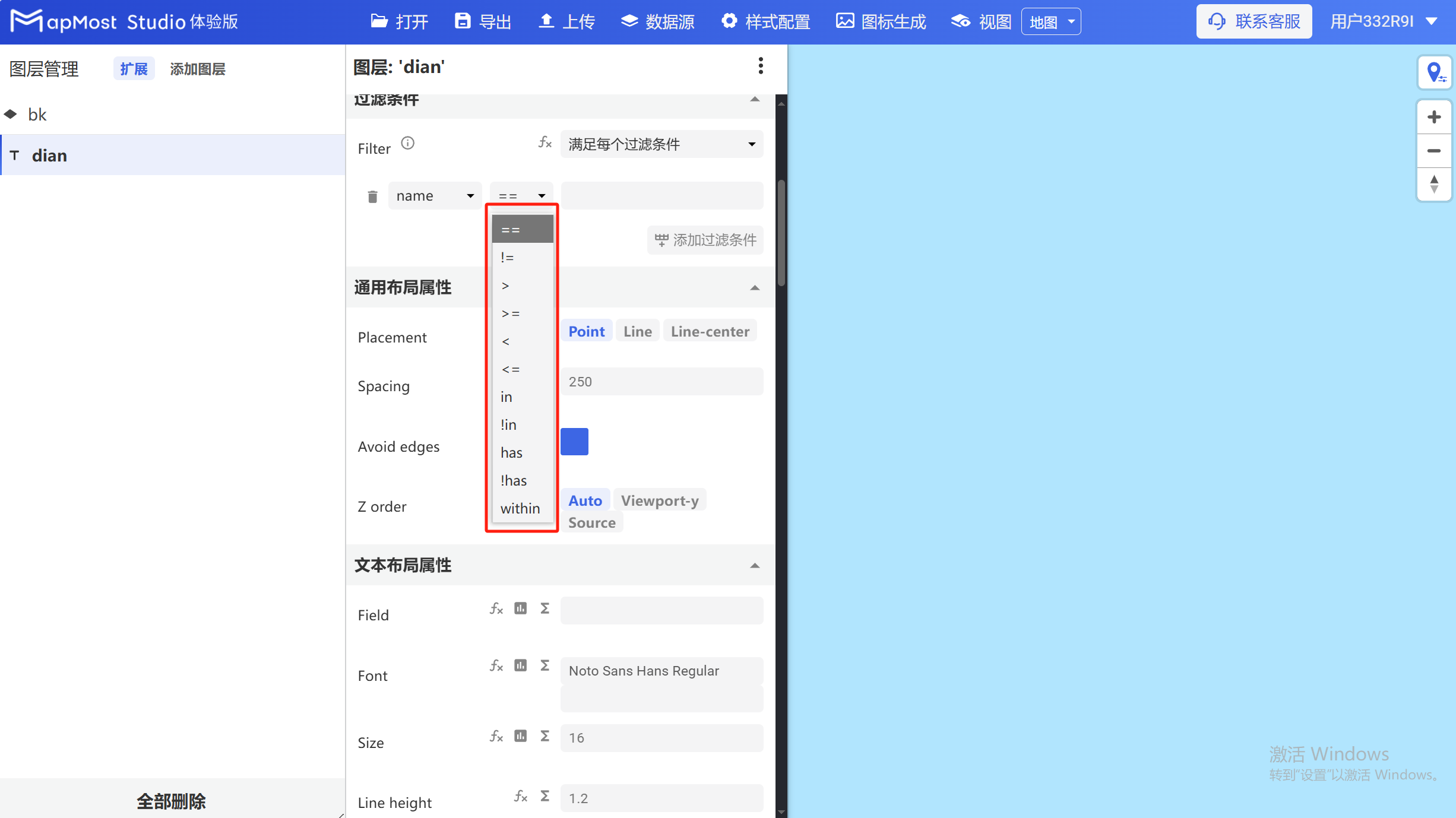
Click the drop-down arrow to select a filtering method:
① equal to
② Not equal to
③ Greater than
④ Greater than or equal to
⑤ Less than
⑥ Less than or equal to
⑦ Contains (such as selecting the "trunk, primary, secondary" data in "fclass")
⑧ Does not include (such as excluding "trunk, primary, secondary" data in "fclass")
⑨ Yes (such as selecting the data in the "Park" field in "name")
⑩ None (such as excluding data in the "park" field in "name")
⑪ Contains (refers to an object being included in an object)
2.5. Fill in the filtering content
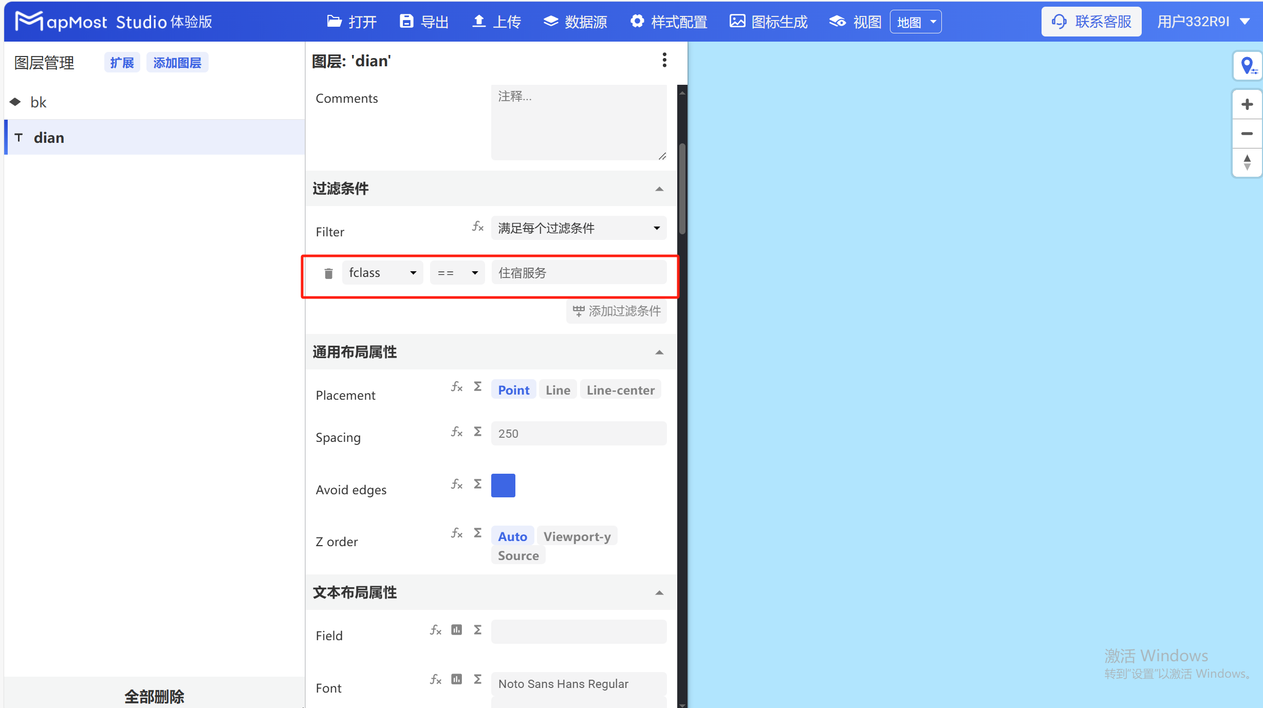
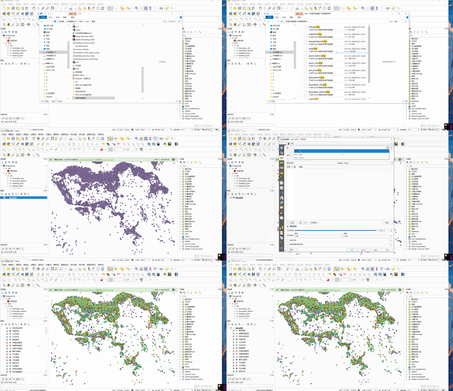
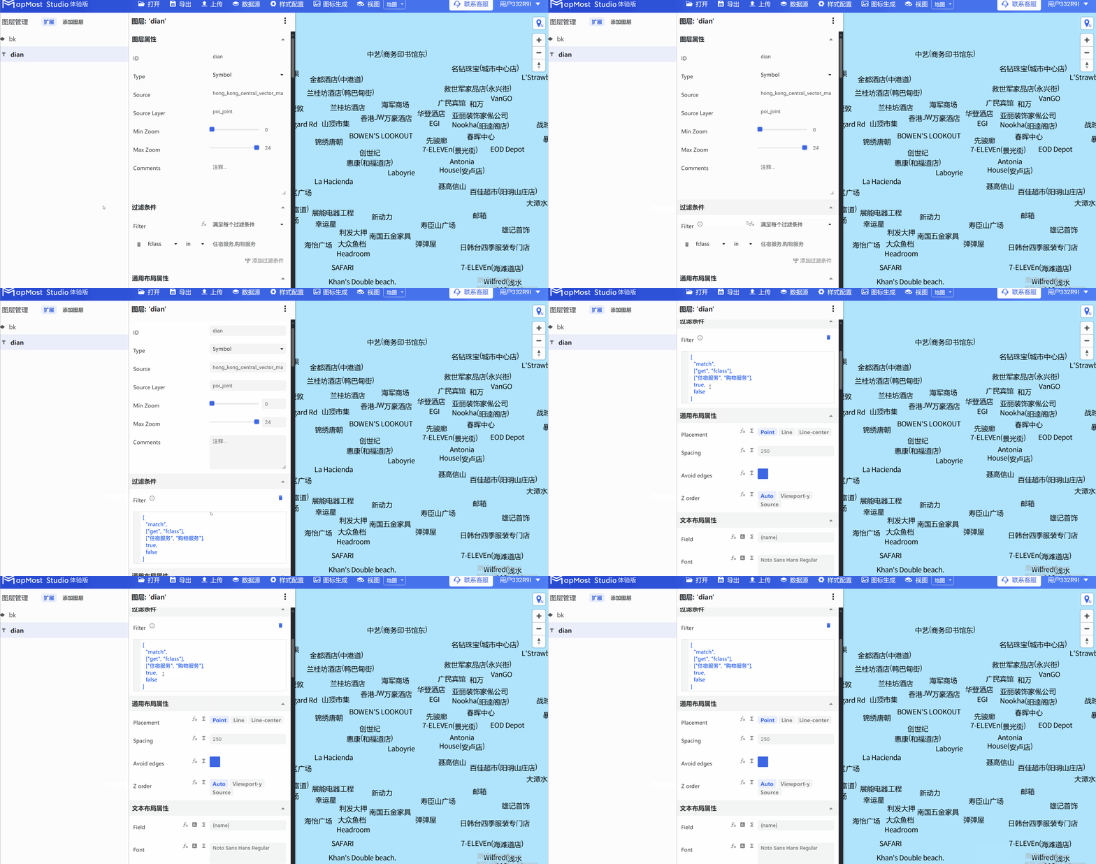
- Click the input box and enter the data fields included in fclass, and the data can be filtered correctly, as shown in Figure 1. If you want to check the field details, you can check it in Qgis software, see Figure 2;
2.6. Fill in complex filtering content
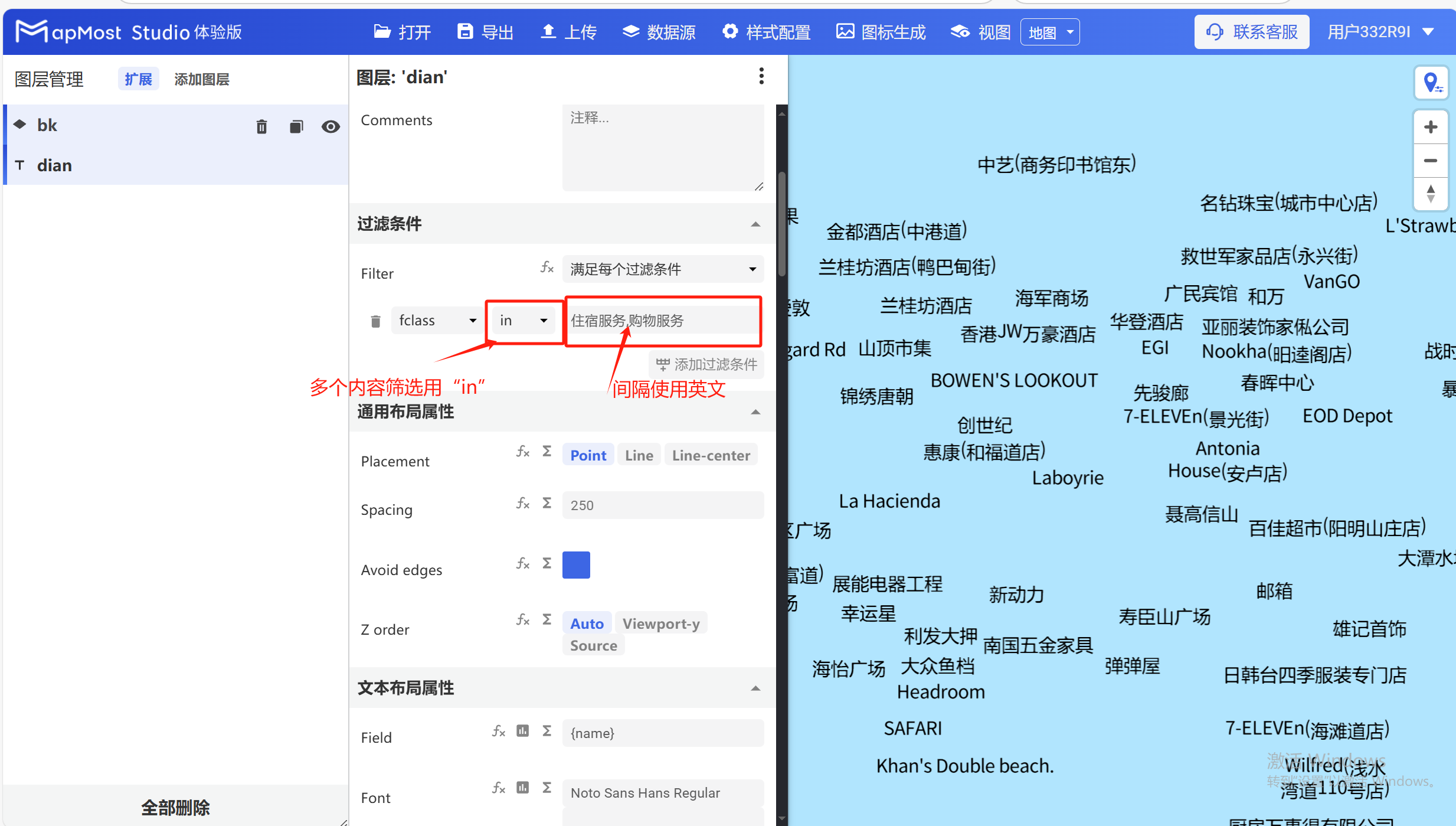
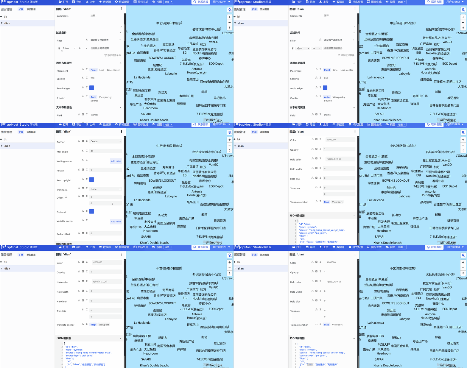
- When filling in complex filtering content, you need to pay attention to the filtering method. Multiple content should be separated by English commas. See Figure 1 for the operation steps. If the entered field information is correct but no data is displayed, you can check whether the field names are consistent in the "json editor module" at the bottom. If they are inconsistent, you need to manually enter the correct field names. The operation steps are shown in Figure 2;
2.7. Convert filter information into expressions
- Due to the limited space in the input box, you can click the "fx" button for more complex filtering conditions to convert them into expressions for conditional input;
3. "Text Layout Properties" module
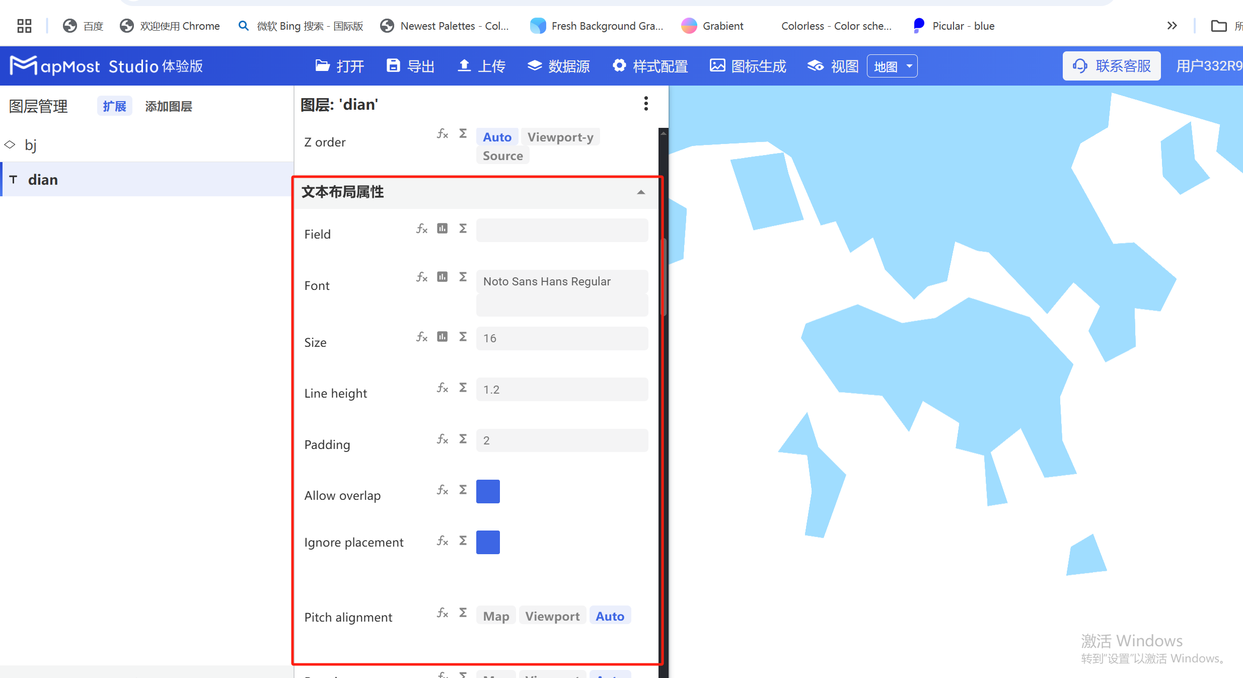
The "Text Layout Properties" module is used to set the size, font, avoidance, alignment and other information of the text in the data;
The initial interface is as follows:
3.1. "Field" parameter setting
- "Field" parameter, enter the field name to display the information fields contained in the data. For data field attribute search, refer to "Icon Point Layer Symbol: 2.3";
3.2. "font" parameter setting
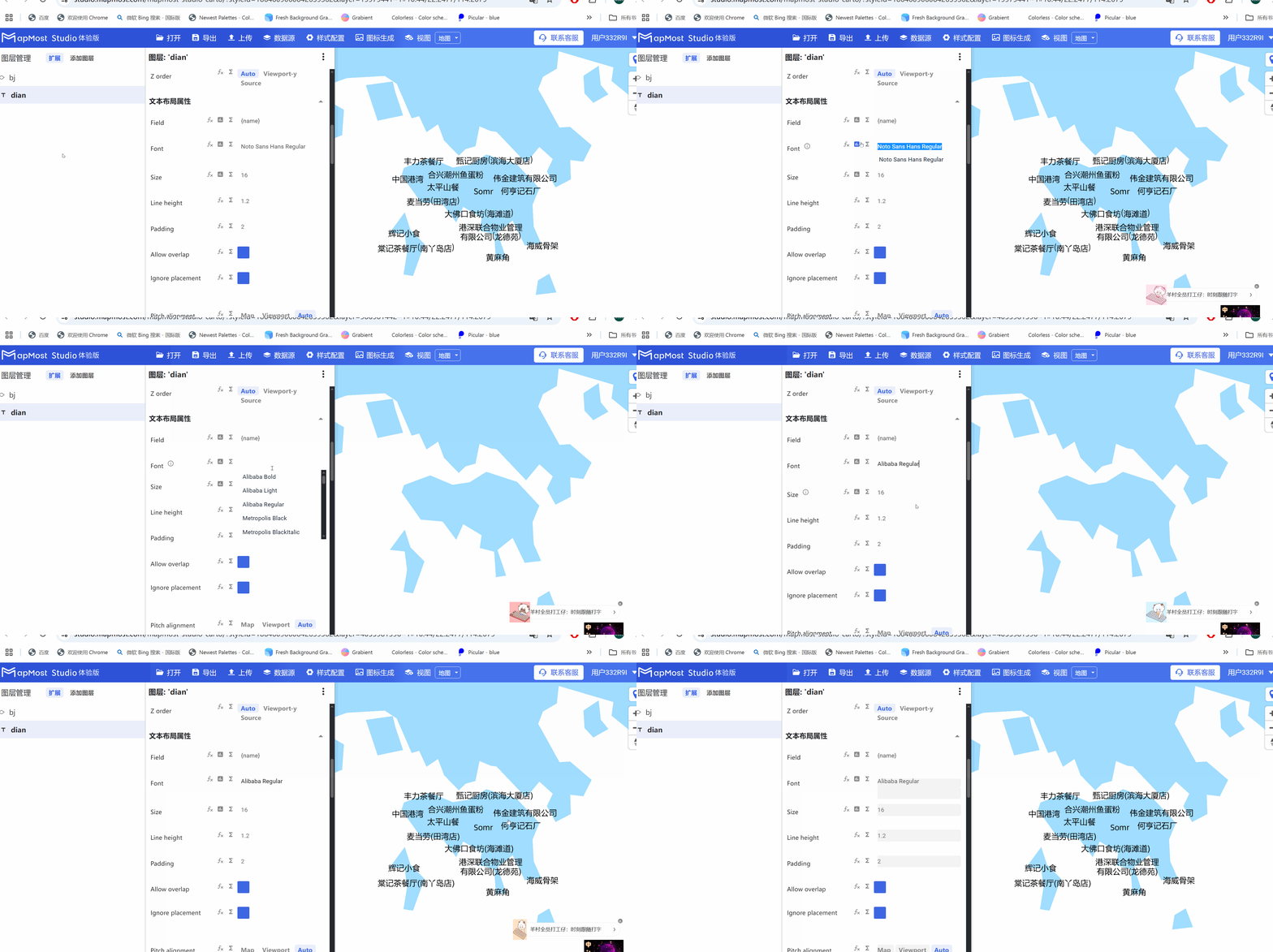
- "font" parameter, set the text font;
3.3. "Size" parameter setting
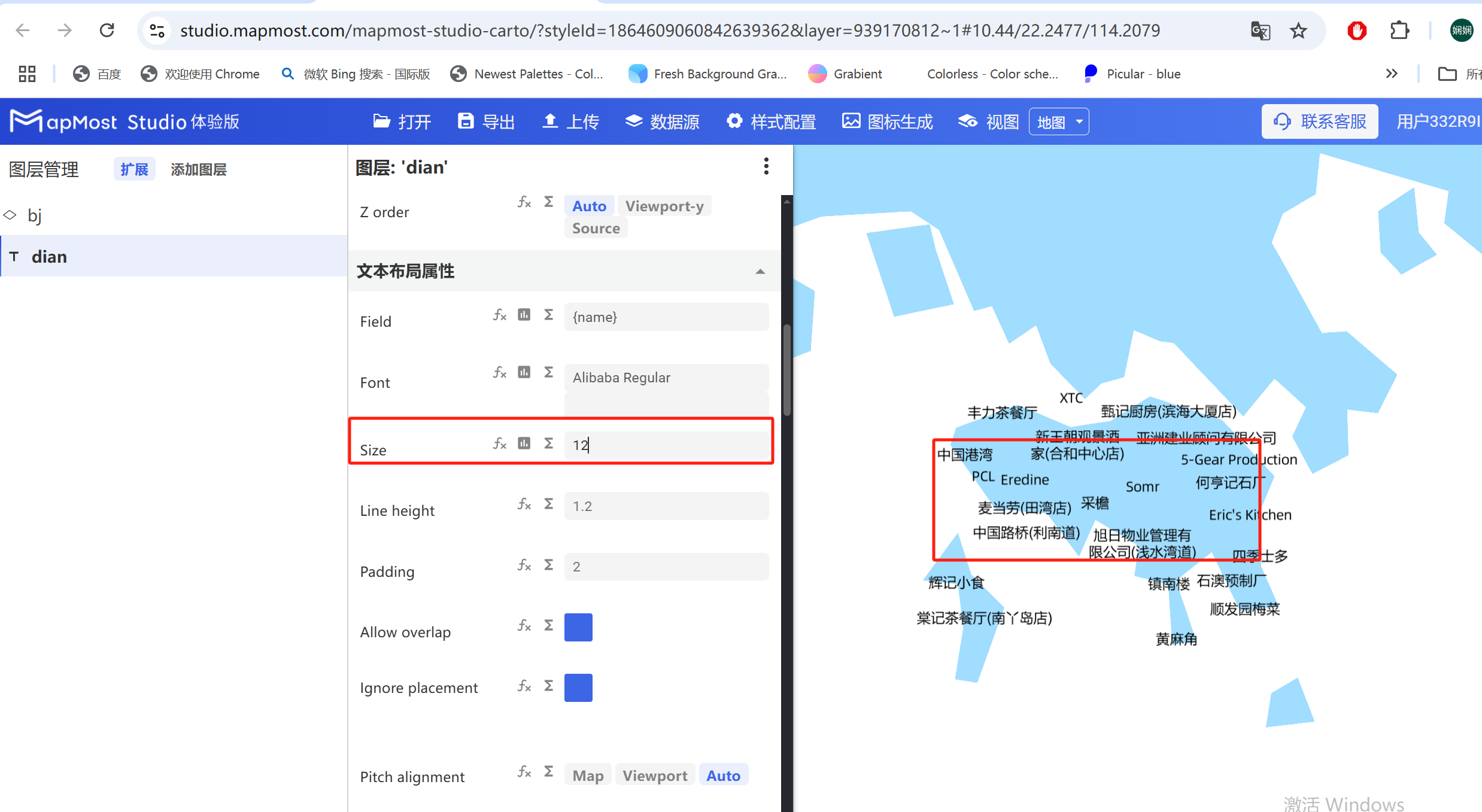
3.3.1. Set font size
- Enter parameters to set the text font size;
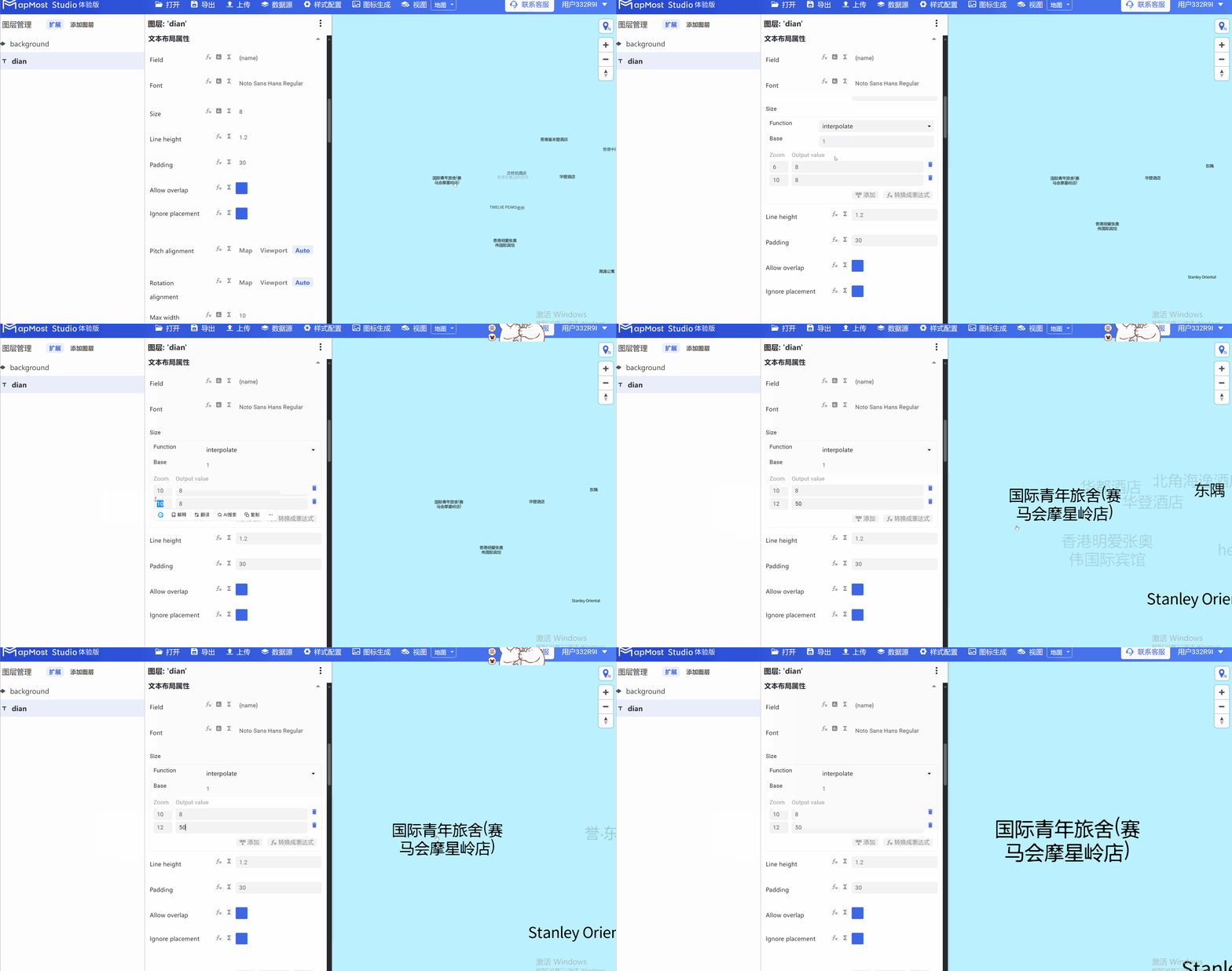
3.3.2. "∑" button
- Click the "∑" button to set the font size to change with the level;
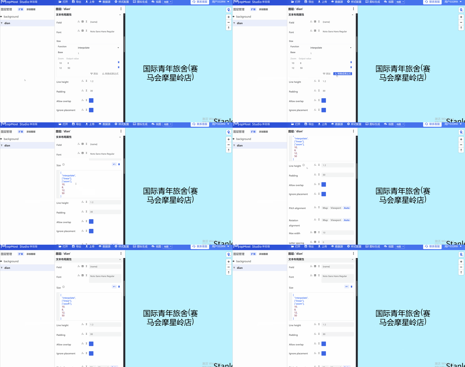
3.3.3. "Convert fx to expression" button
- Click the "Convert fx to expression" button to convert the parameter information into an expression;
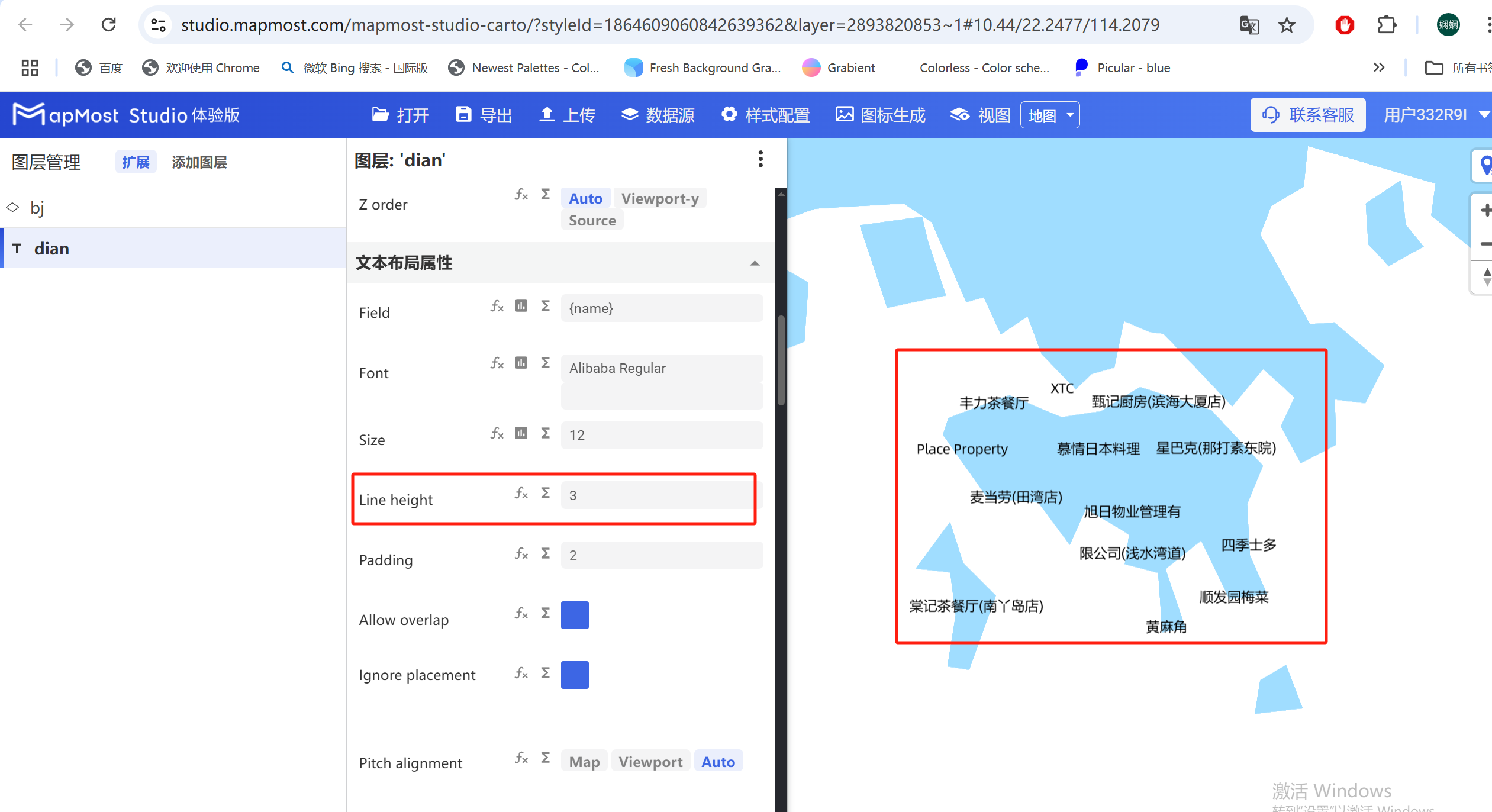
3.4. "Line height" parameter setting
- "Line height" parameter, sets text line spacing;
3.5. "Padding" parameter setting
- "Padding" parameter, sets the size of the text border. The larger the parameter value, the more data is avoided. You can use this parameter to adjust the data density;
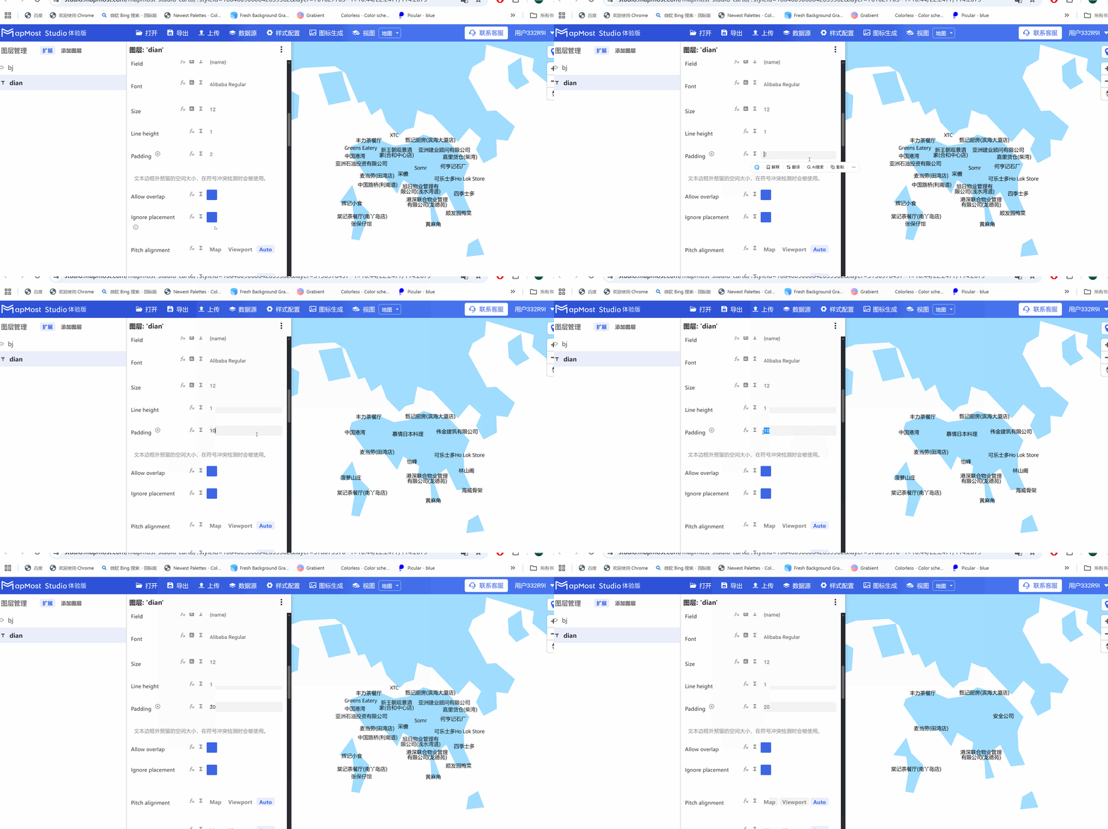
3.6. "Allow overlap" parameter setting
- The "Allow overlap" parameter sets whether the text is displayed when it overlaps with other symbols or text;
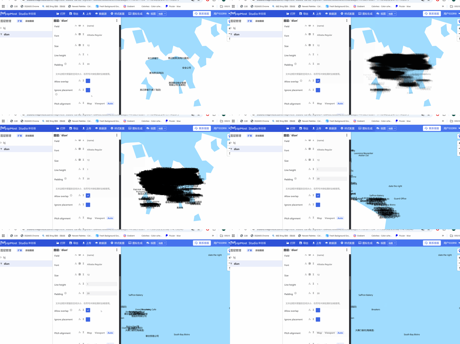
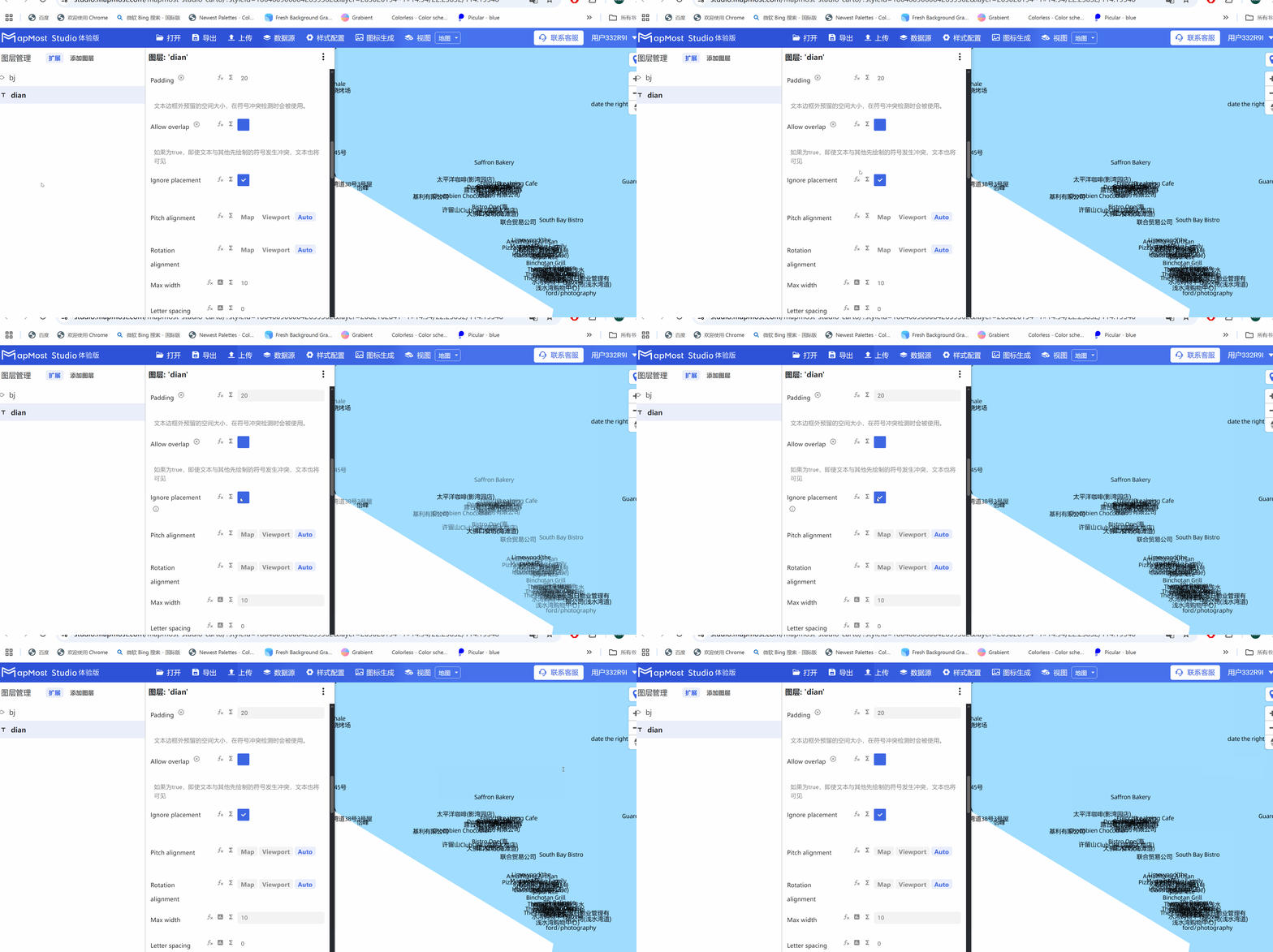
3.7. "Ignore overlap" parameter setting
- "Ignore overlap" parameter, when setting the text and text overlap, whether the text is displayed;
3.8. "Pitch alignment" parameter setting
- "Pitch alignment" parameter, set the text alignment direction, "Map" faces the map, "Viewport" faces the viewport, and "Auto" automatically recognizes the orientation;
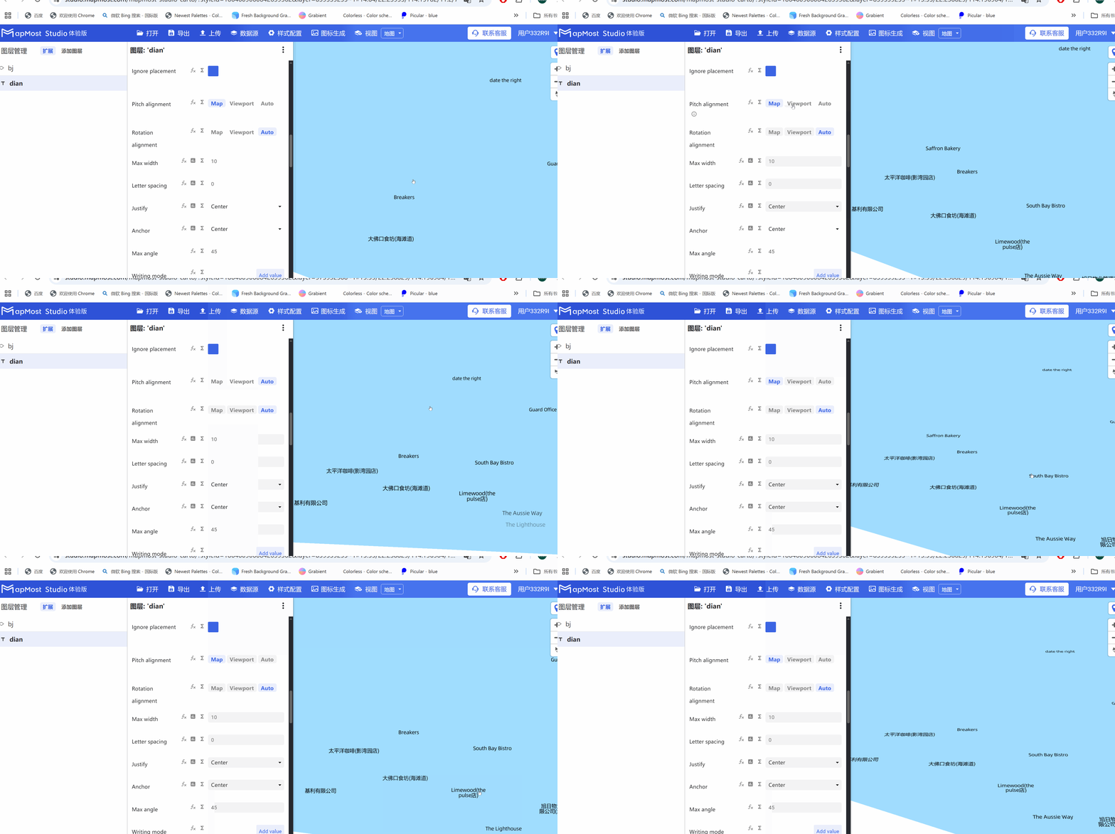
3.9. "Rotation alignment" parameter setting
- "Rotation alignment" parameter, set the text rotation direction, "Map" faces the map, "Viewport" faces the viewport, and "Auto" automatically recognizes the orientation;
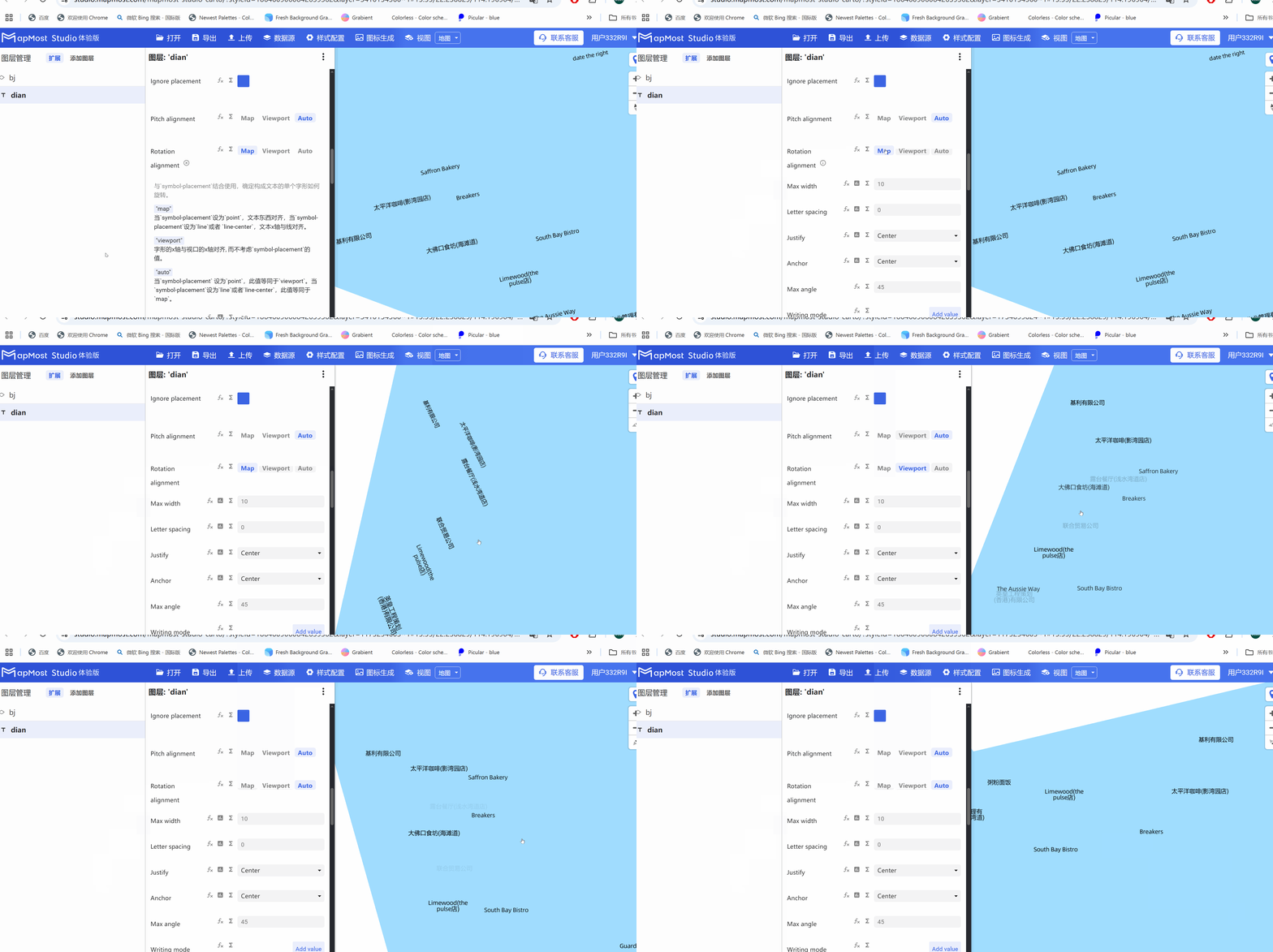
3.10. "Max width" parameter setting
- "Max width" parameter, set the text width;
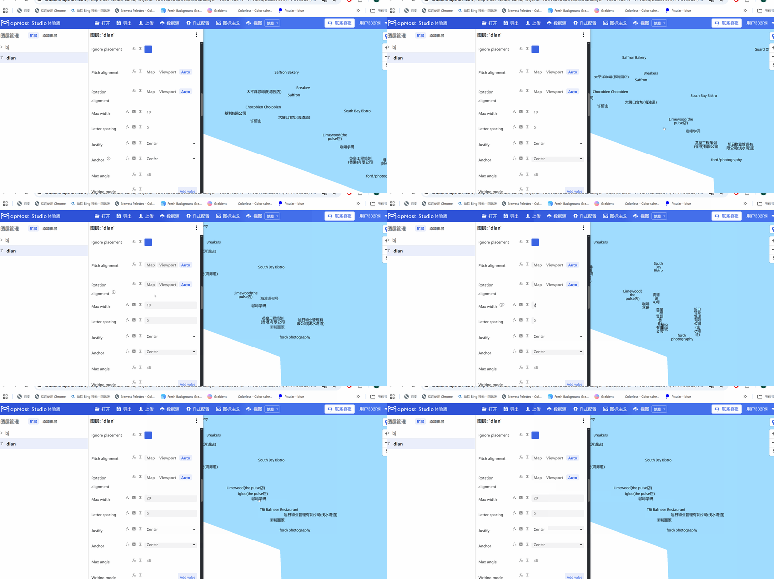
3.11. "Letter spacing" parameter setting
- "Letter spacing" parameter, sets the text spacing;
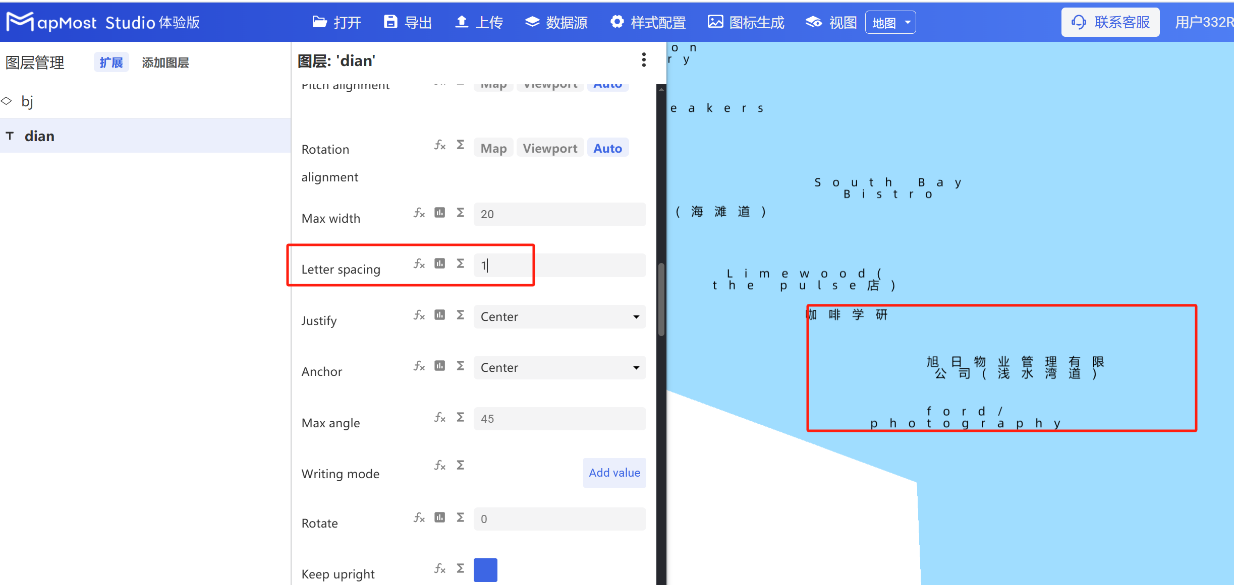
3.12. "Justify" parameter setting
- "Justify" parameter, sets the alignment of text;
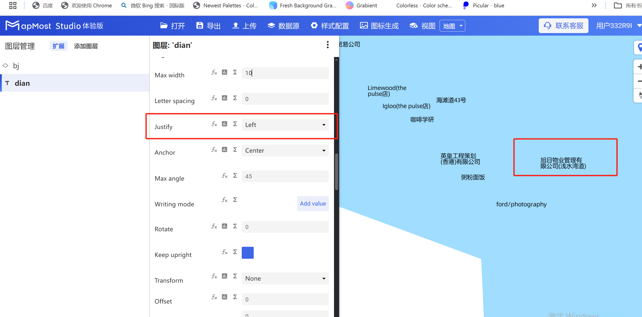
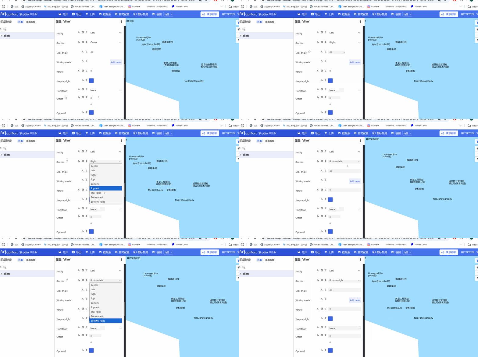
3.13. "Anchor" parameter setting
- "Anchor" parameter, sets the relative position of text and anchor point;
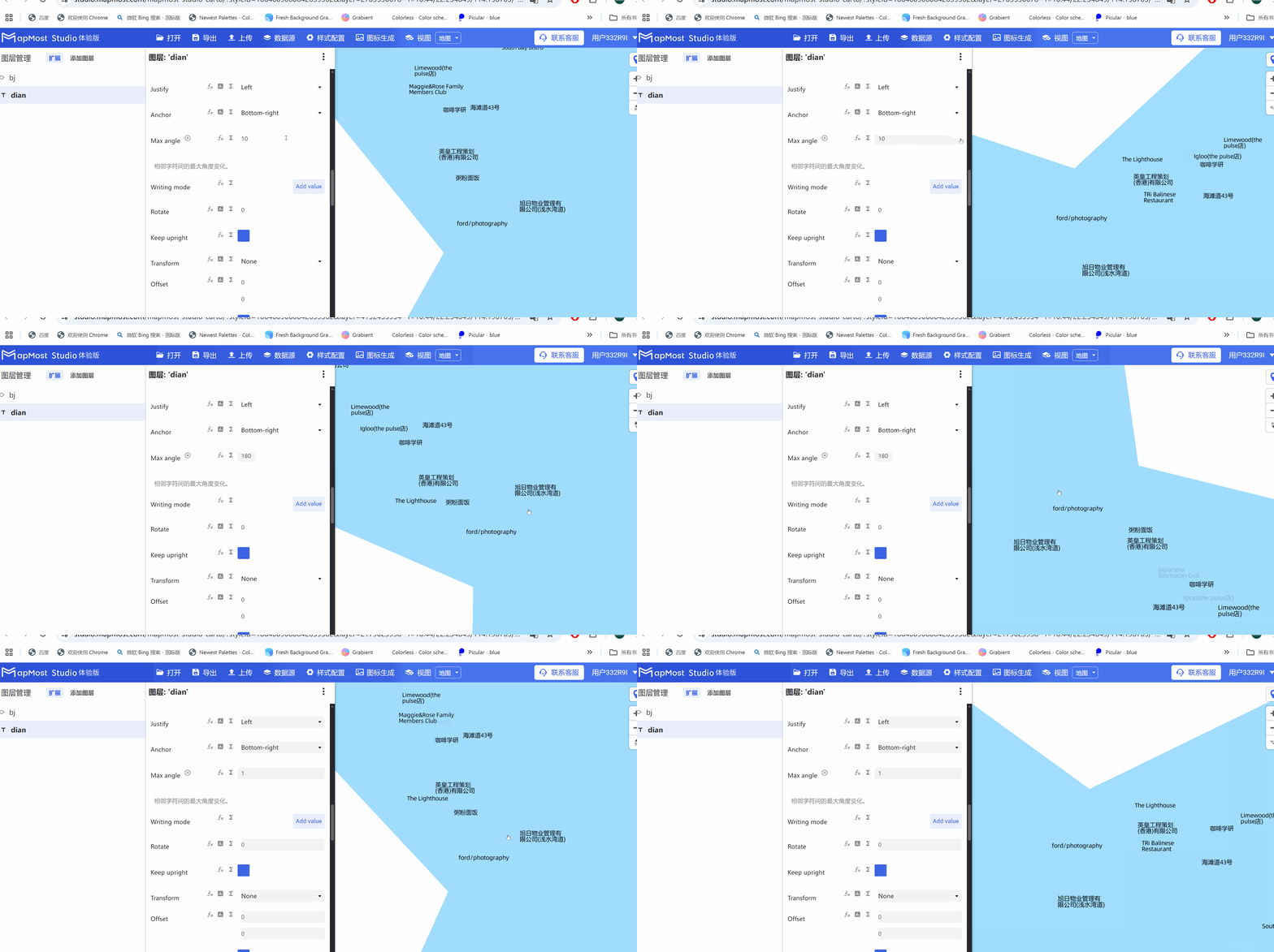
3.14. "Max angle" parameter setting
- "Max angle" parameter sets the maximum angle change between adjacent characters;
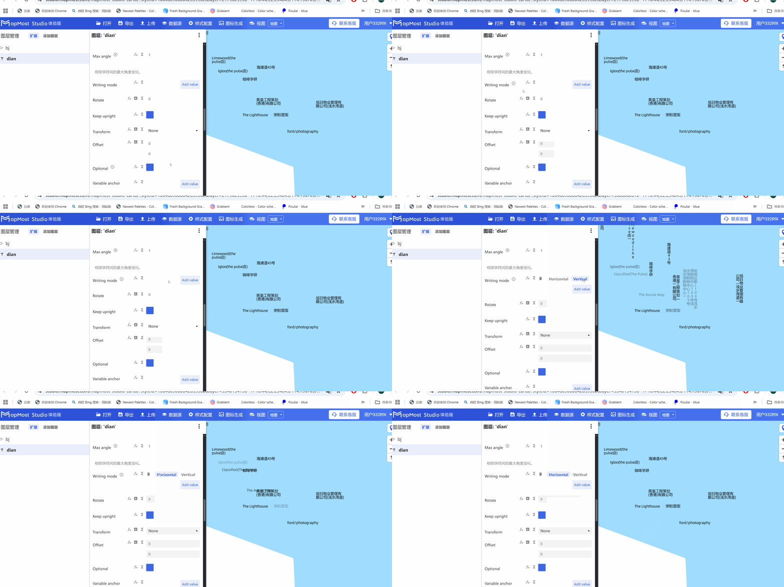
3.15. "Writing mode" parameter setting
- "Writing mode" parameter, sets the text writing direction;
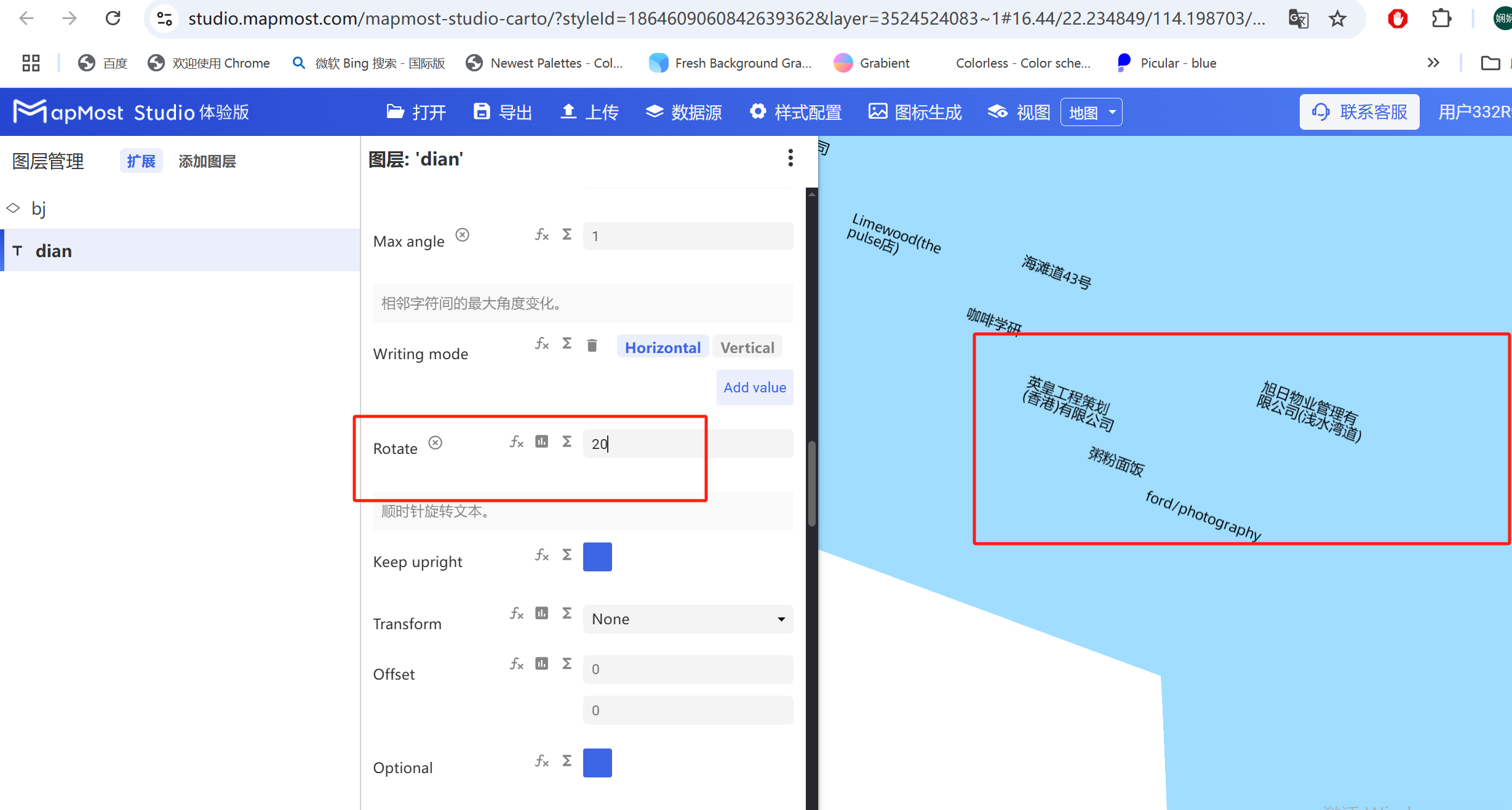
3.16. "Rotate" parameter setting
- "Rotate" parameter, rotate text angle;
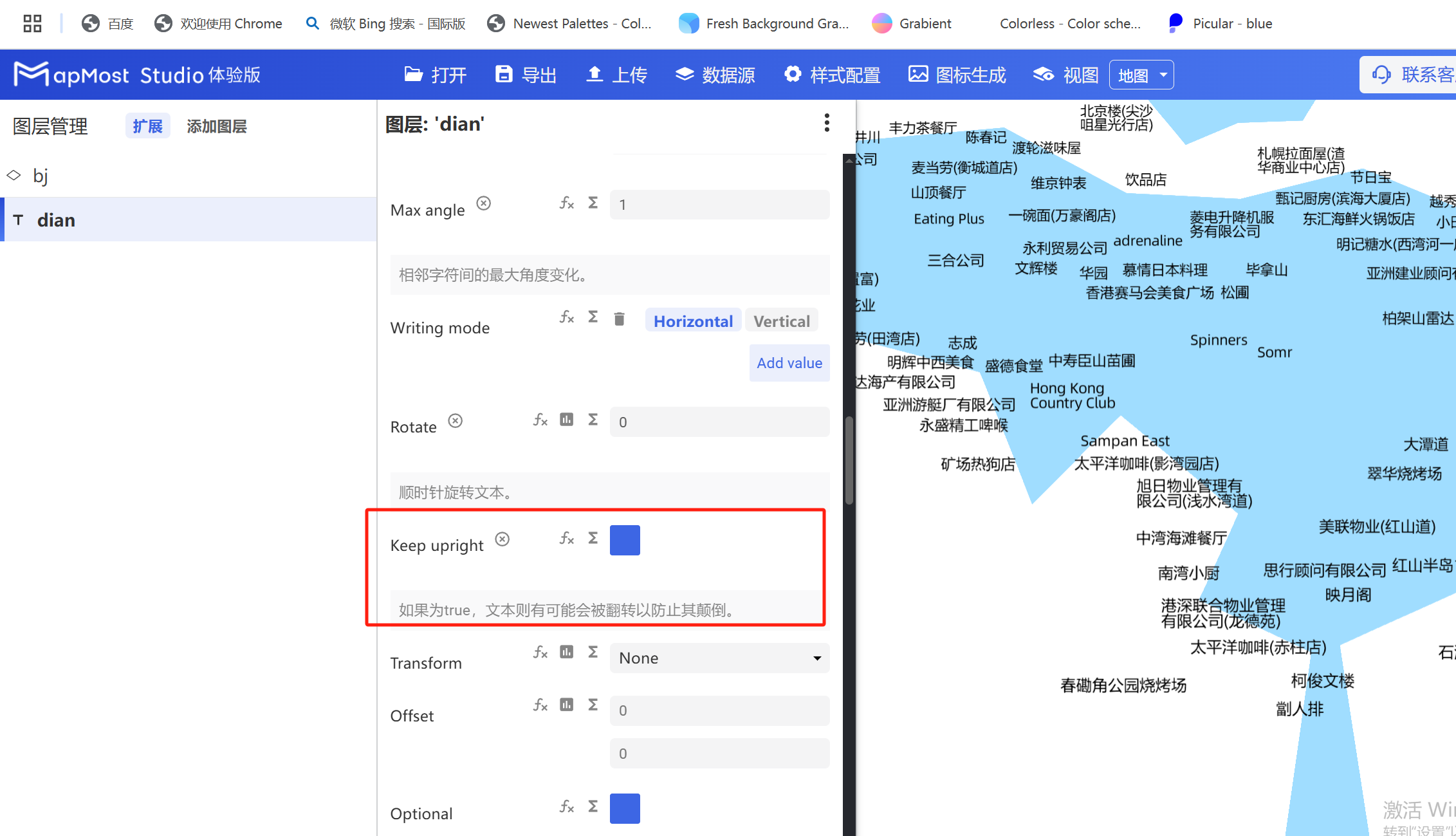
3.17. "Keep upright" parameter setting
- "Keep upright" parameter to prevent text from being reversed;
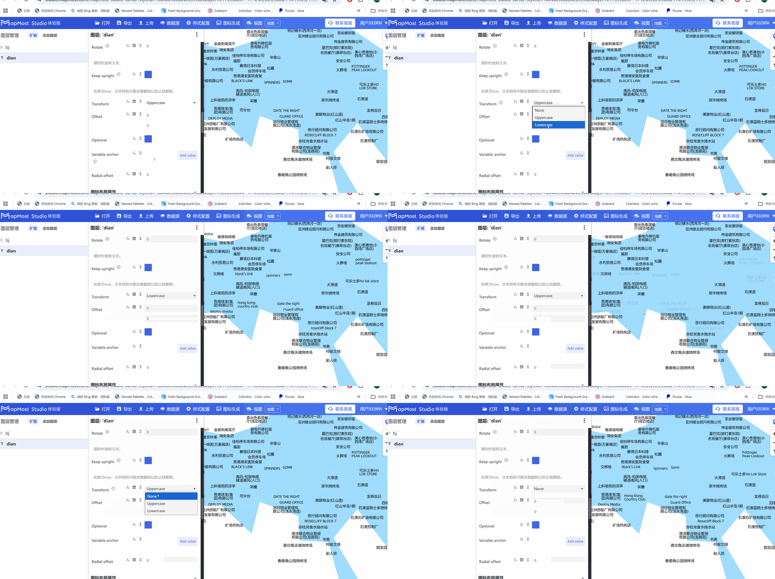
3.18. "Transform" parameter setting
- "Transform" parameter, convert English text to uppercase and lowercase;
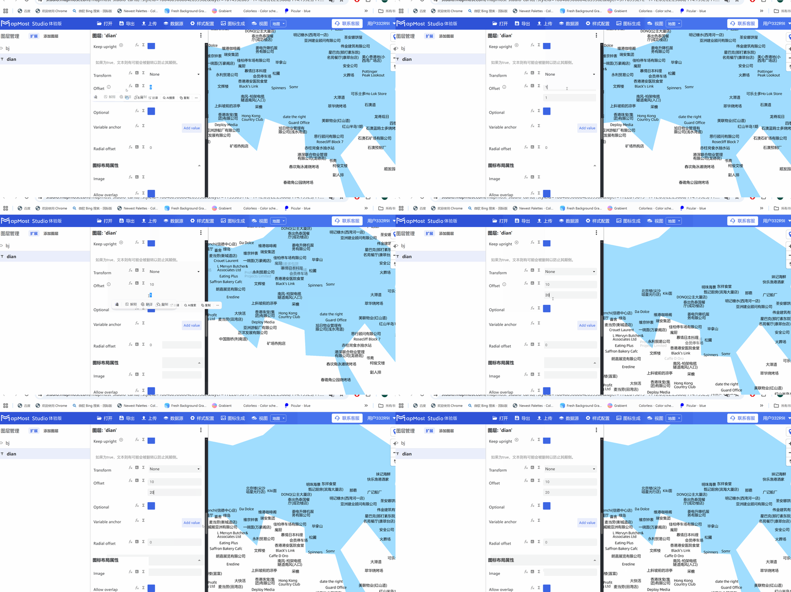
3.19. "Offset" parameter setting
- "Offset" parameter, sets the offset of the text in the X\Y direction;
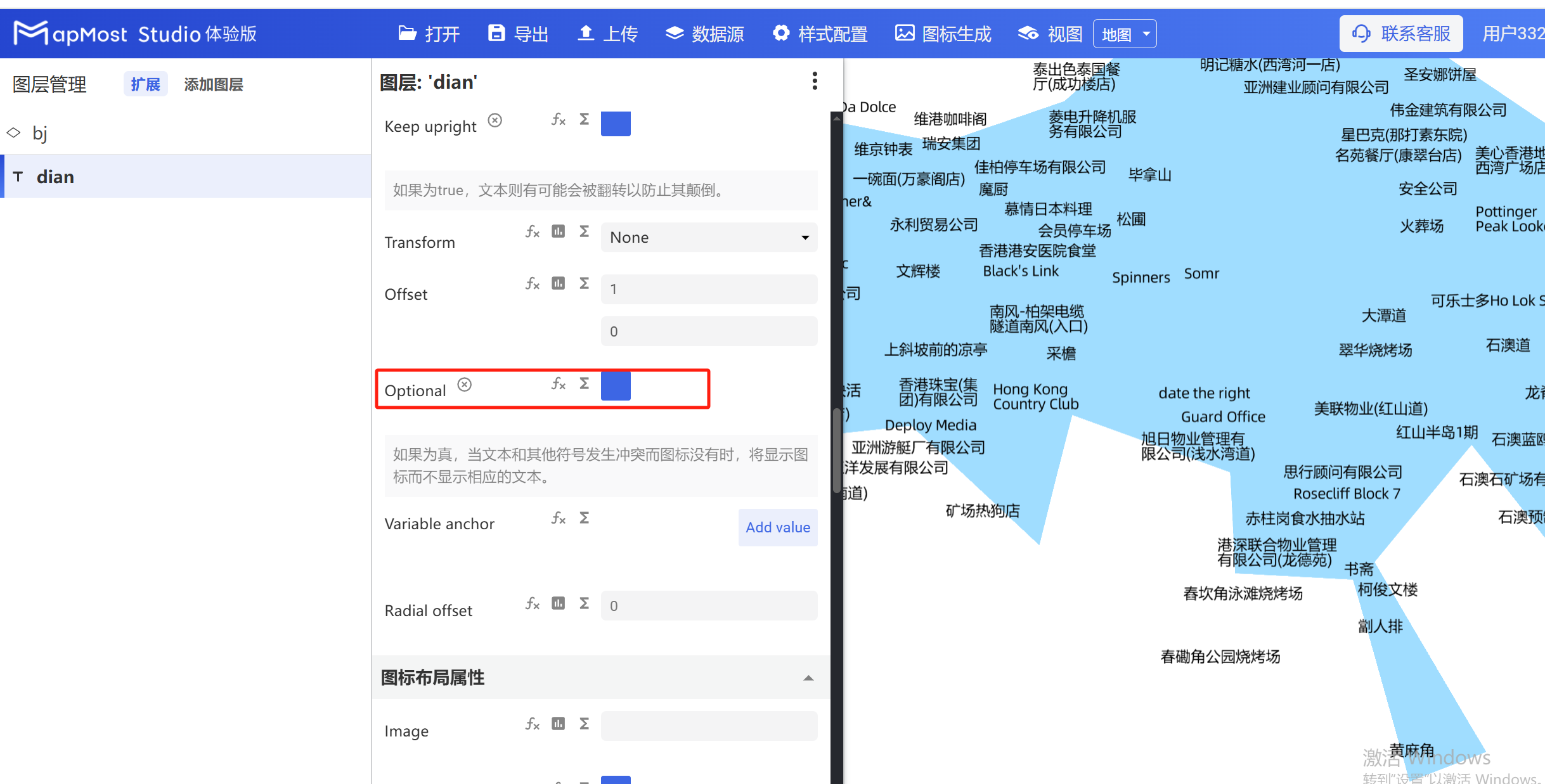
3.20. "Optional" parameter setting
- "Optional" parameter, an icon is displayed when the text conflicts with other characters;
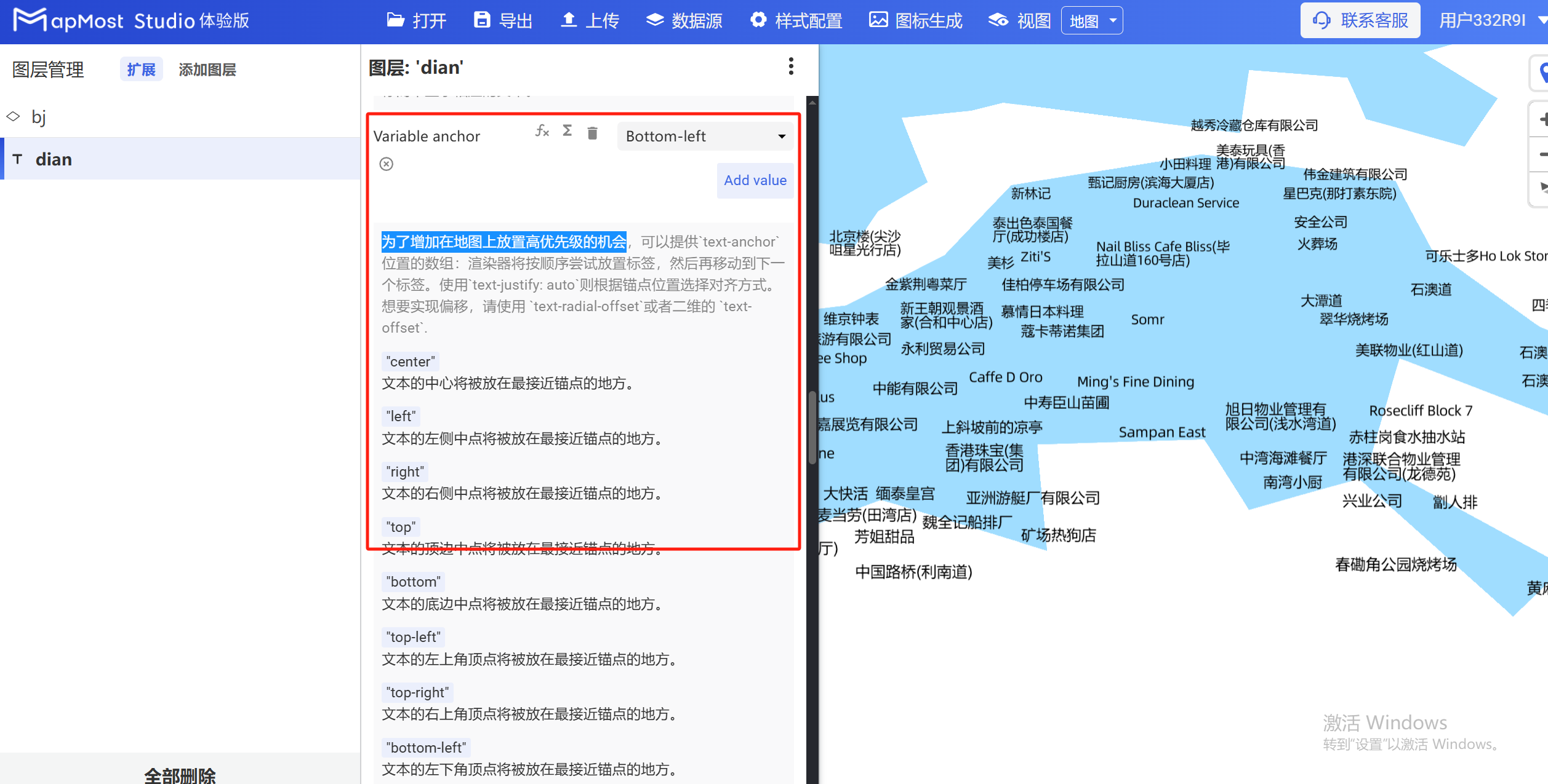
3.21. "Variable anchor" parameter setting
- "Variable anchor" parameter, sets text priority;
3.22. "Radial offset" parameter setting
- "Radial offset" parameter, sets the alignment of text in the direction of the anchor point;
4. "General Layout Properties" module
The "General Layout Properties" module is used to set parameters such as text display mode, anchor point distance, and rendering order in the data.
The initial interface is as follows:
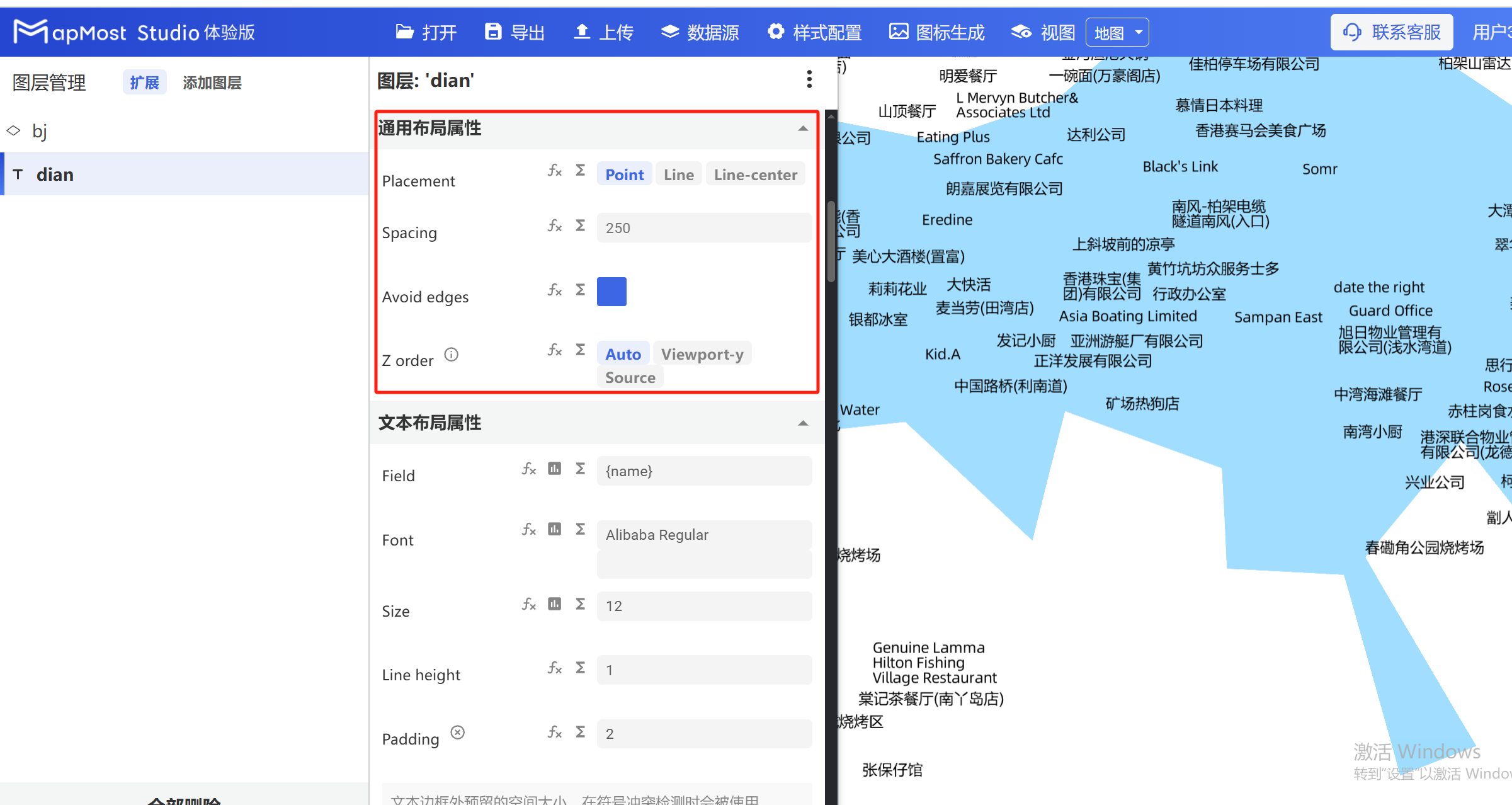
4.1. "Placement" parameter setting
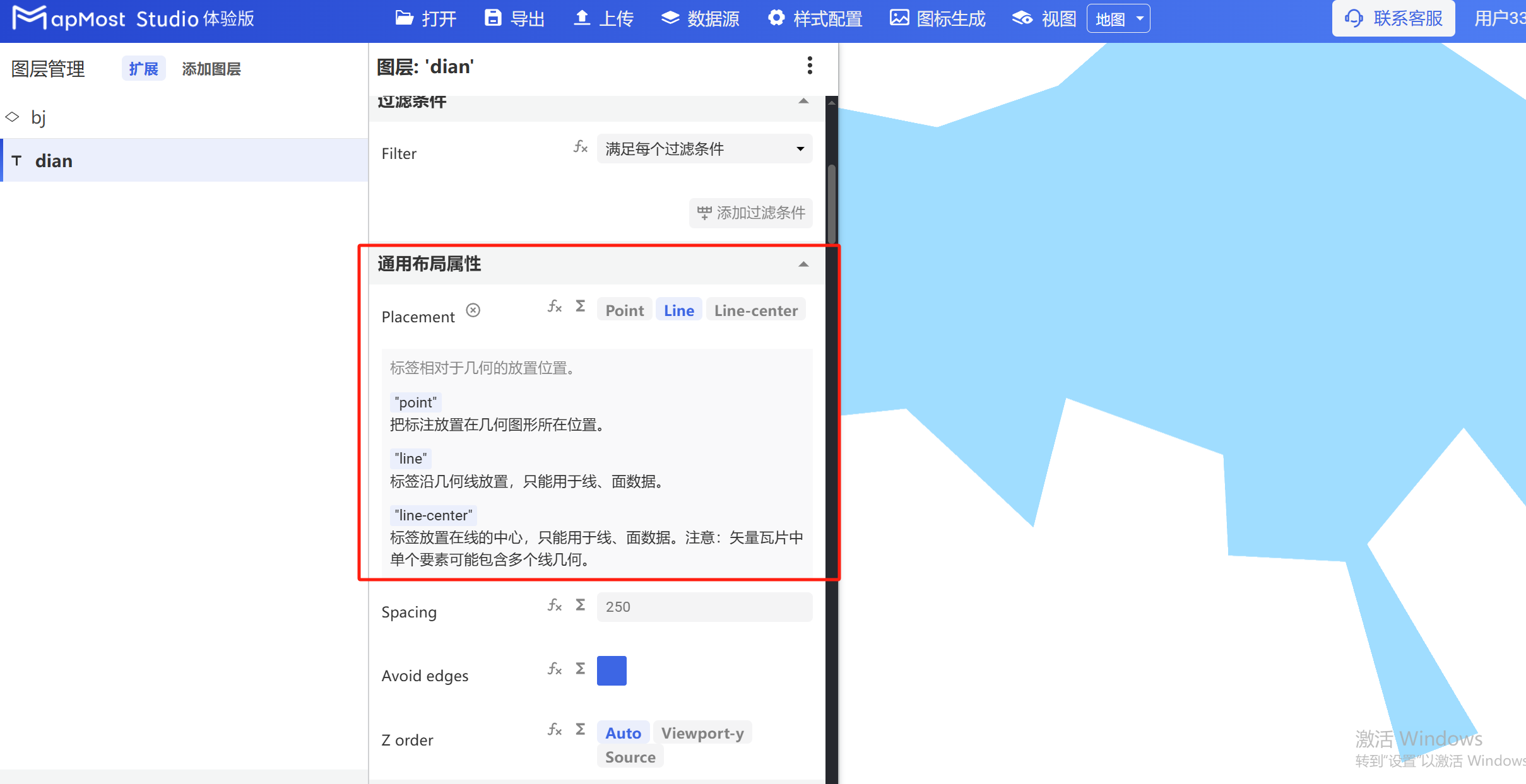
- "Placement" parameter, select the position where the text is placed, whether it is placed on a point or on a line;
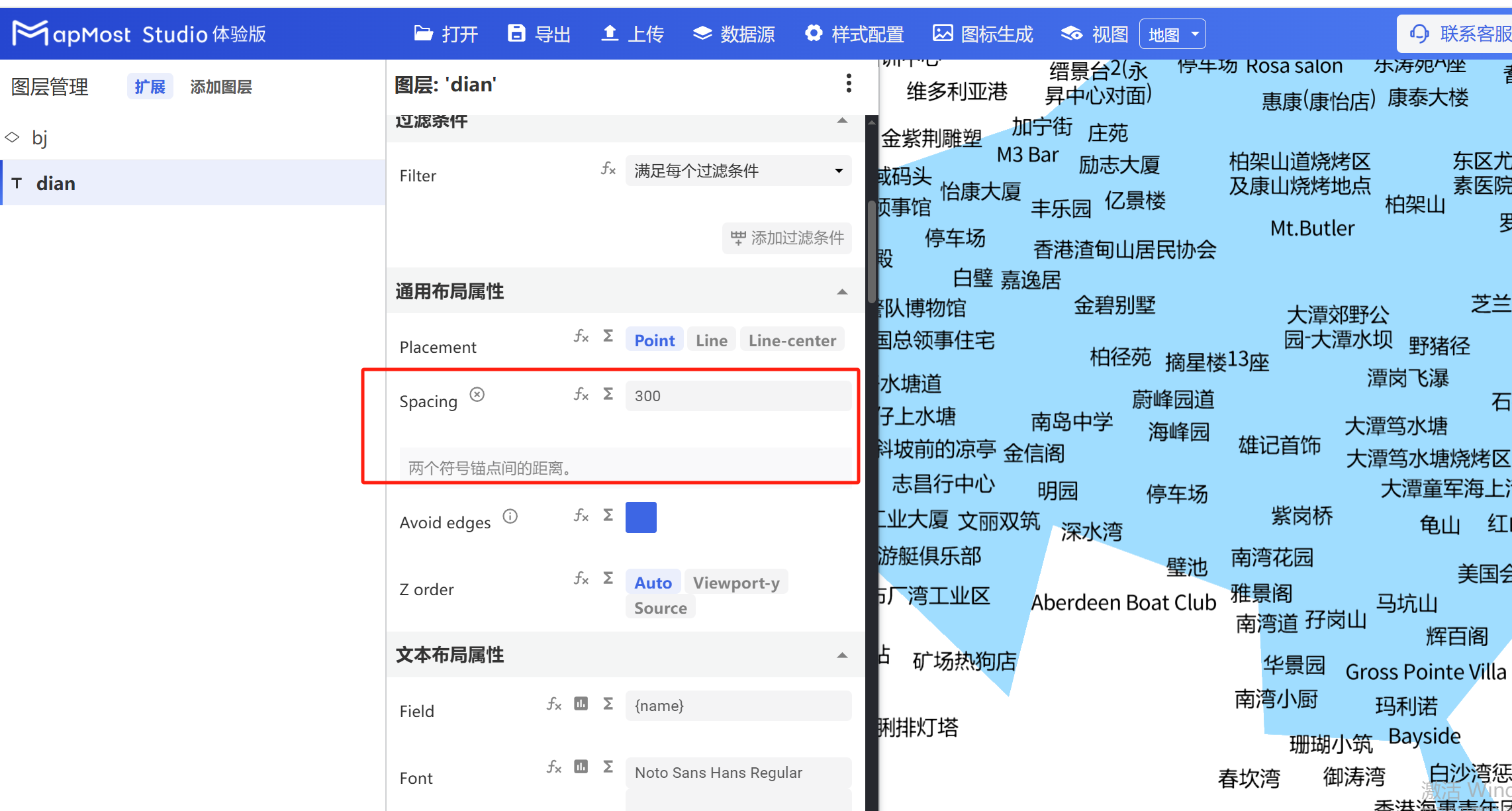
4.2. "Spacing" parameter setting
- "Spacing" parameter, sets the distance between two anchor points;
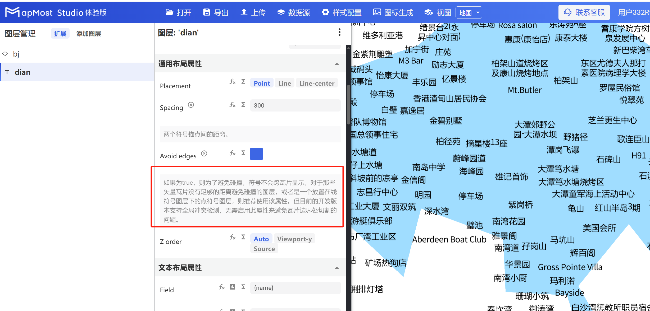
4.3. "Avoid edges" parameter setting
- "Avoid edges" parameter sets the collision method between text and tiles;
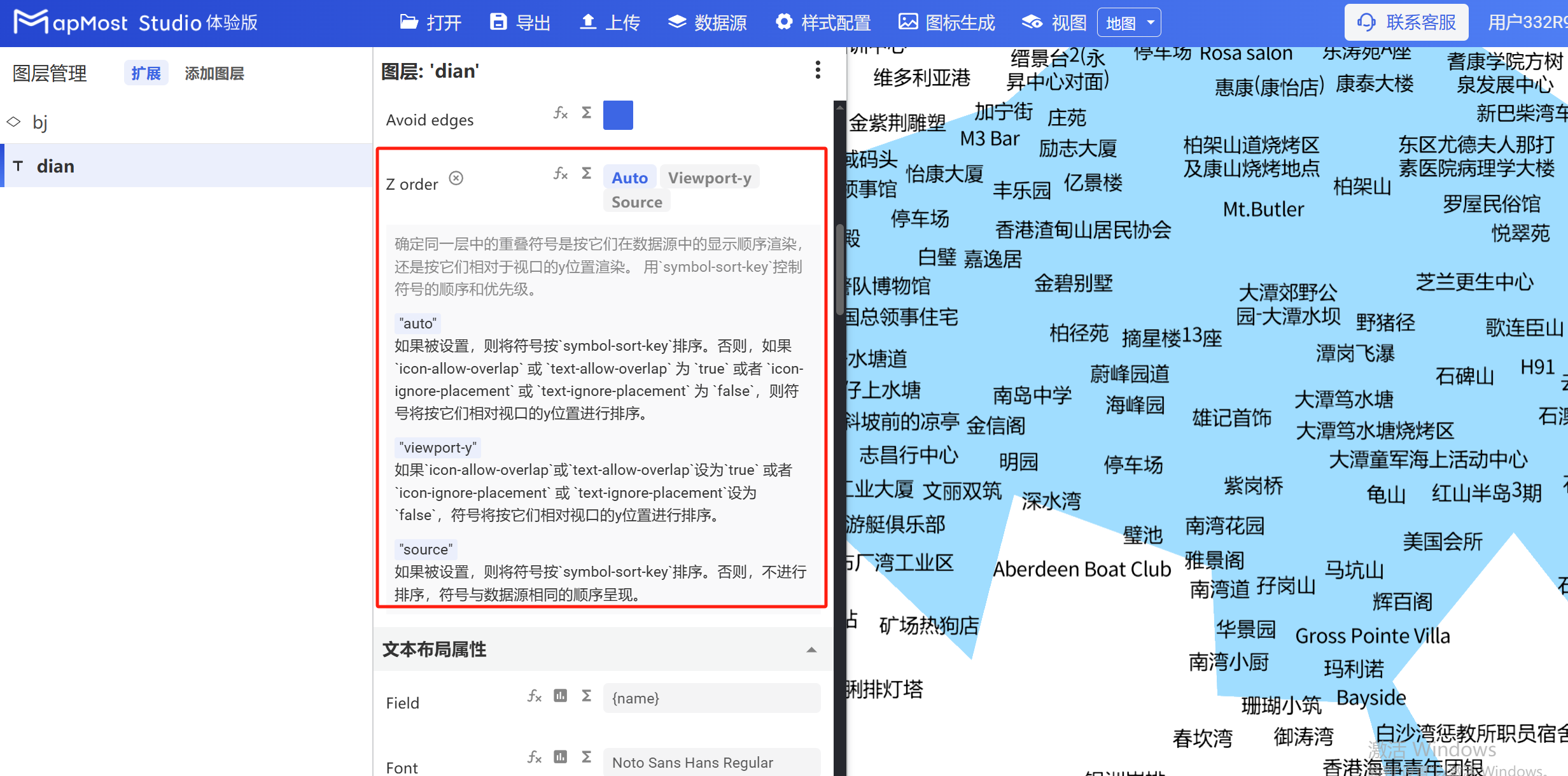
4.4. "Z order" parameter setting
- "Z order" parameter, sets the data rendering order;
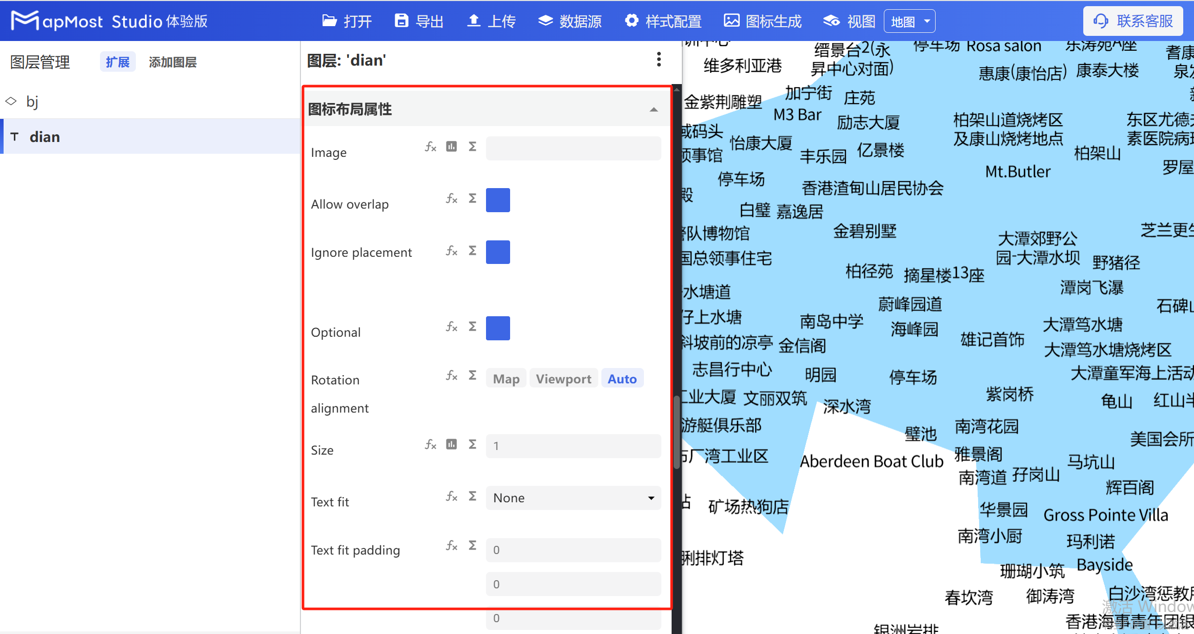
5. "Icon layout properties" module
The "Icon Layout Properties" module is used to set parameters such as icon, icon size, icon offset, and icon rotation.
The initial interface is as follows:
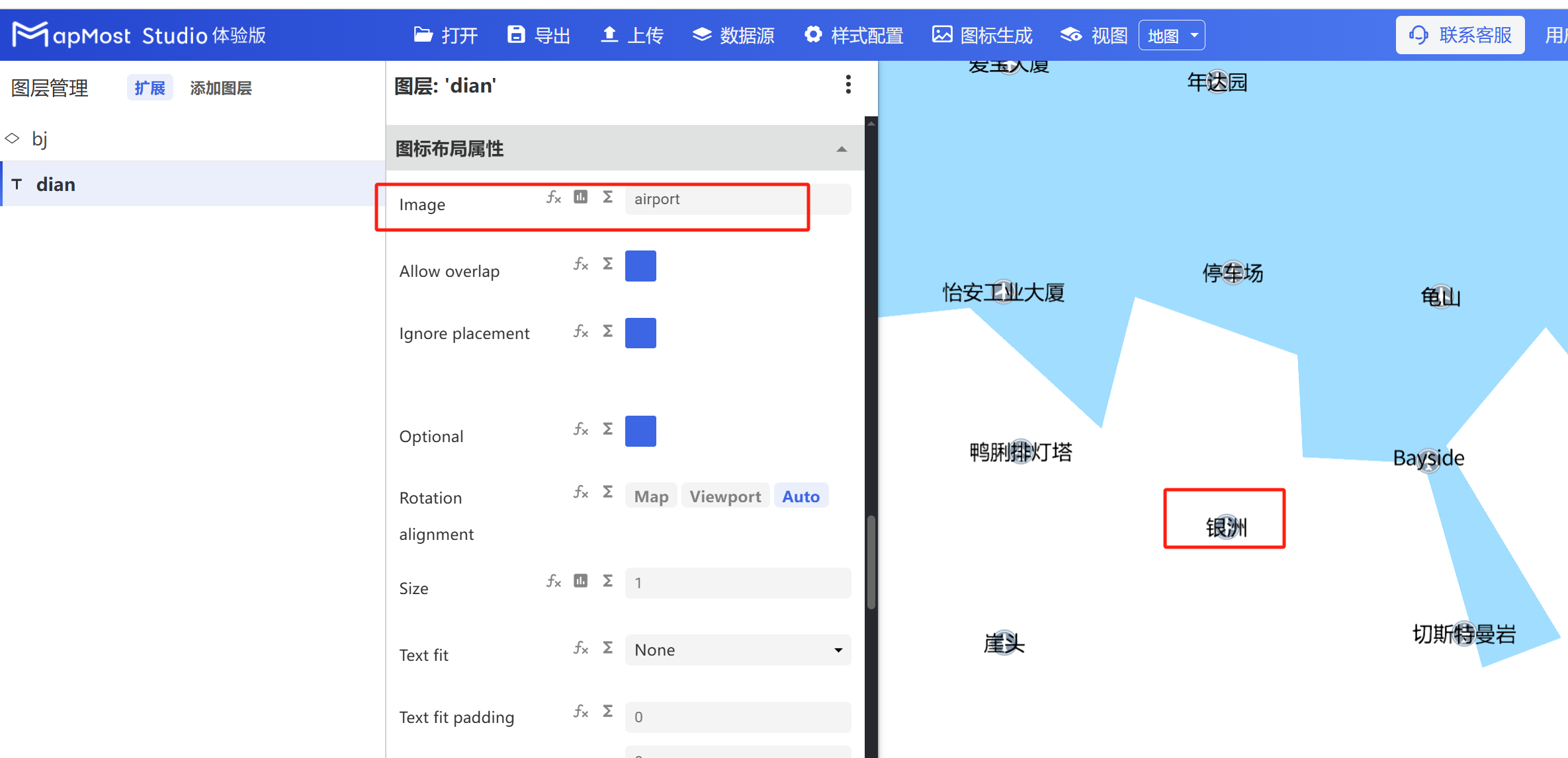
5.1. "Image" parameter setting
- "Image" parameter supports icon selection;
5.2. "Allow overlap" parameter setting
- "Allow overlap" parameter, set the icon to be visible when the icon conflicts;
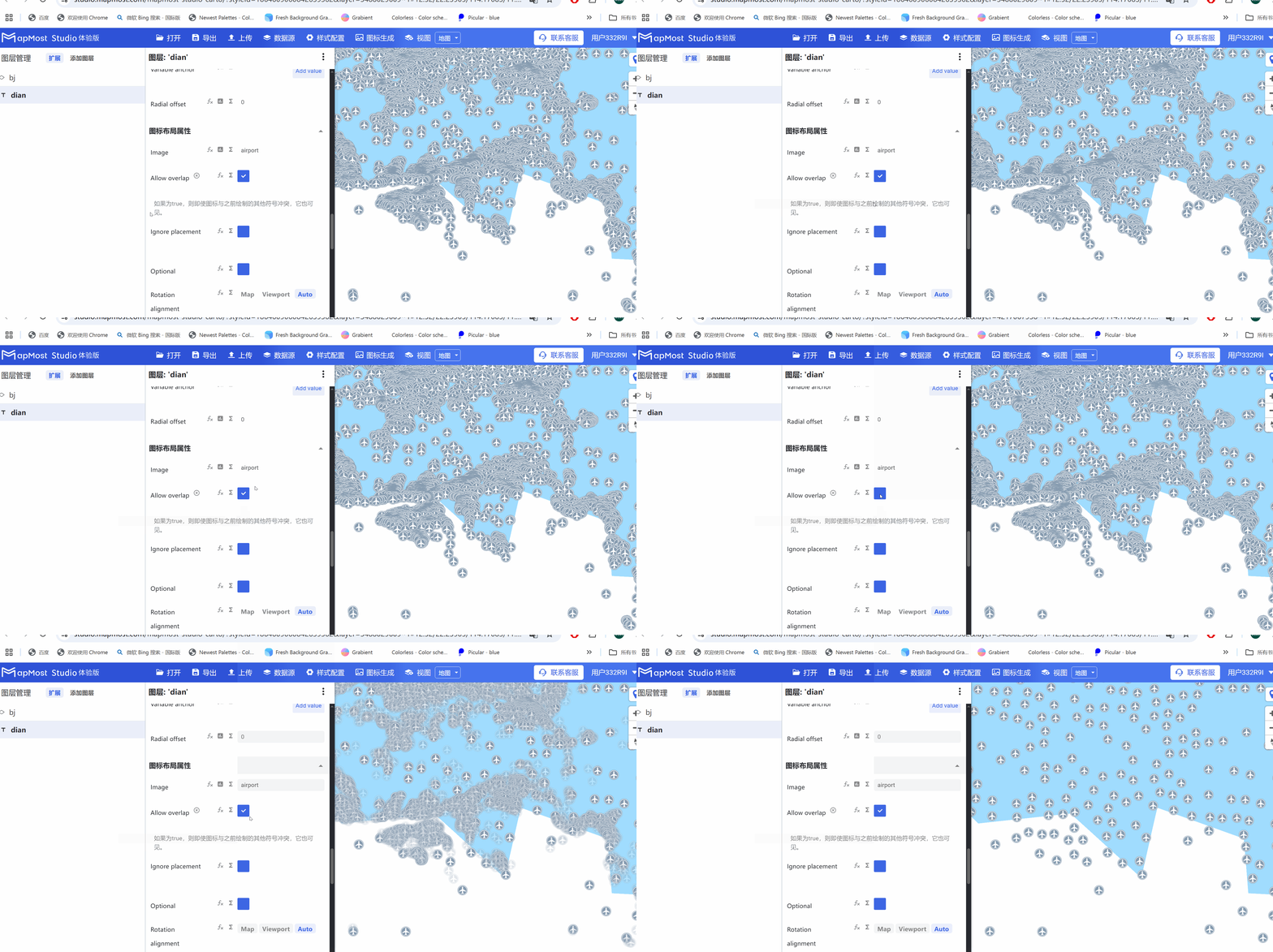
5.3. "Ignore placement" parameter setting
- "Ignore placement" parameter, when the set icon conflicts with other icons, other icons will still be visible;

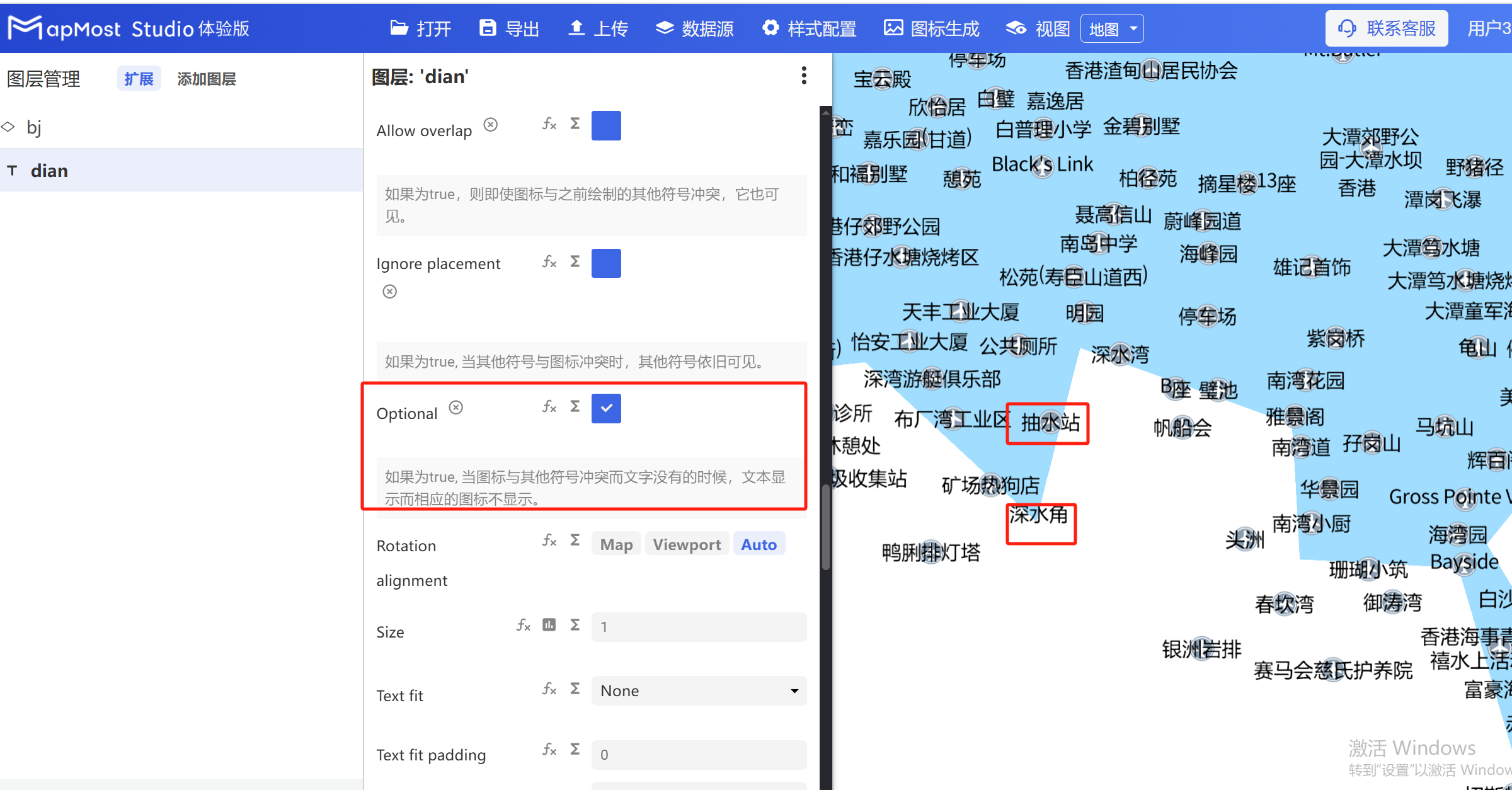
5.4. "Optional" parameter setting
- "Optional" parameter, when the icon conflicts with the text, the text will be displayed instead of the icon;
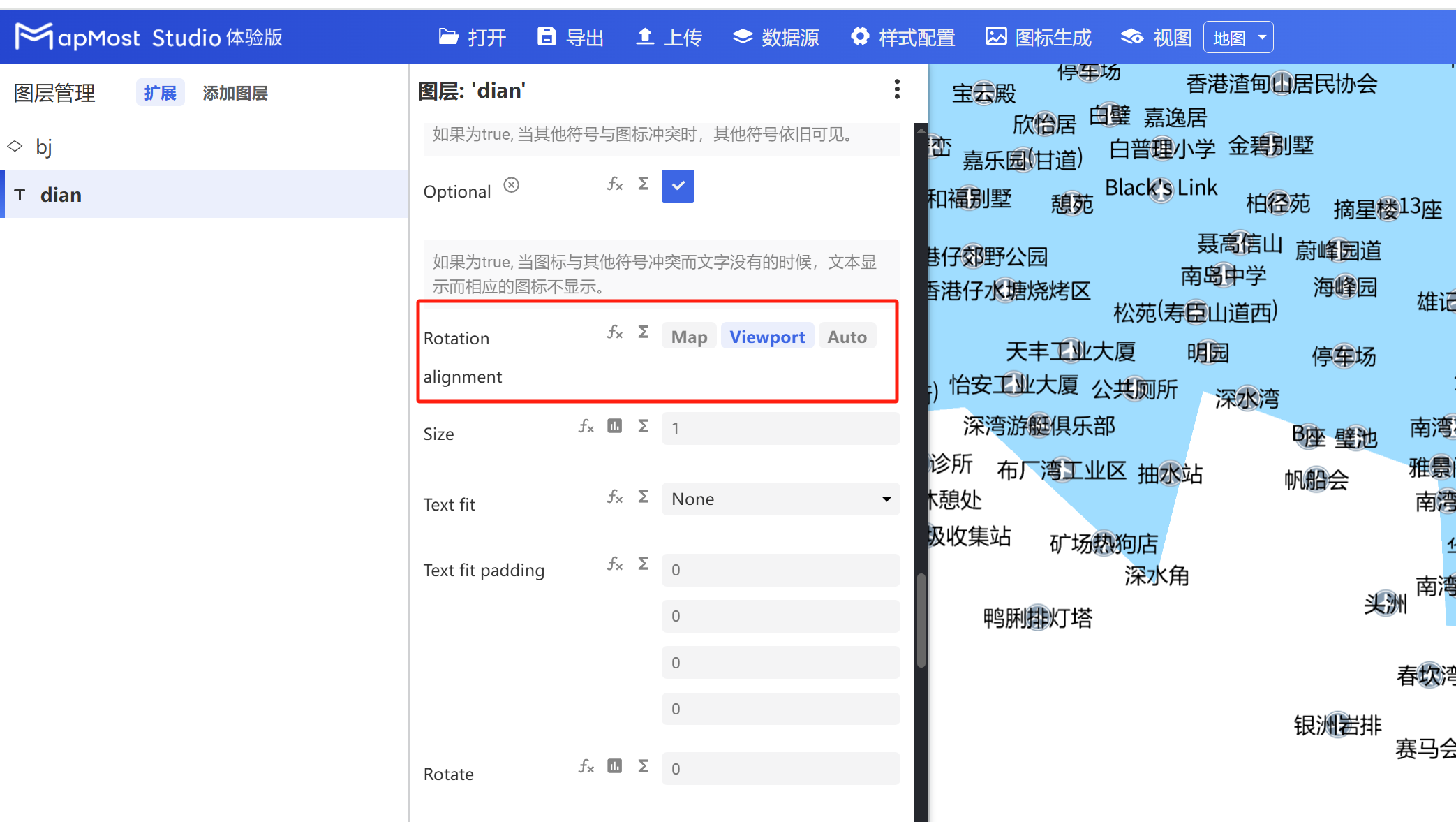
5.5. "Rotation alignment" parameter setting
- "Rotation alignment" parameter, refer to "Icon Point Layer Symbol: 3.9";
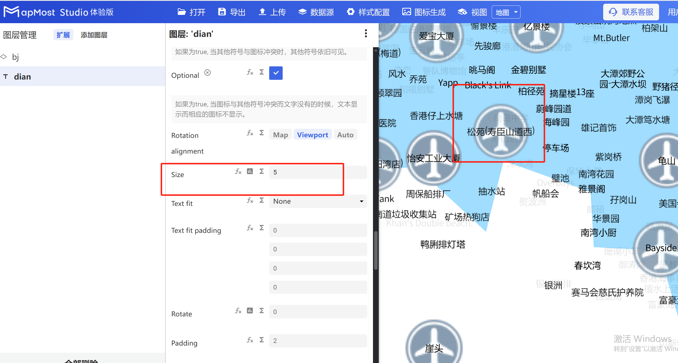
5.6. "Size" parameter setting
- "Size" parameter, set the icon size;
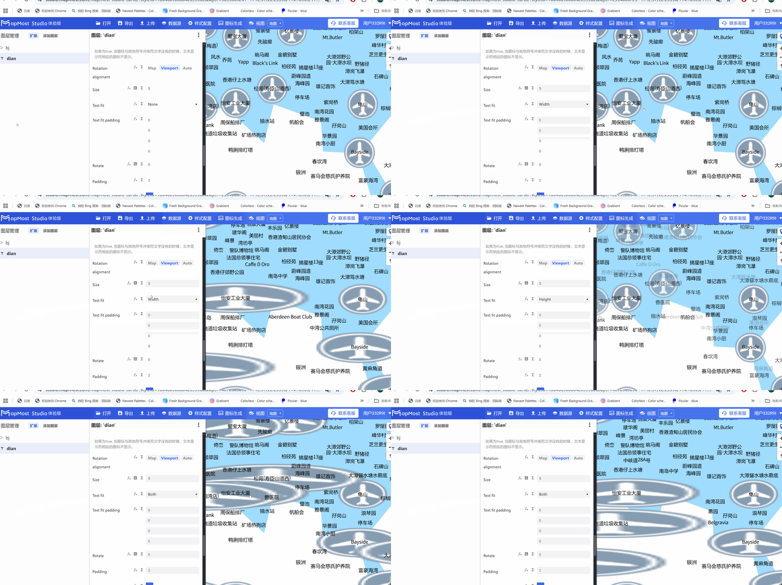
5.7. "Text fit" parameter setting
- The "Text fit" parameter sets the icon size to adapt to the text length, which is often used to adapt the text box length to the text length;
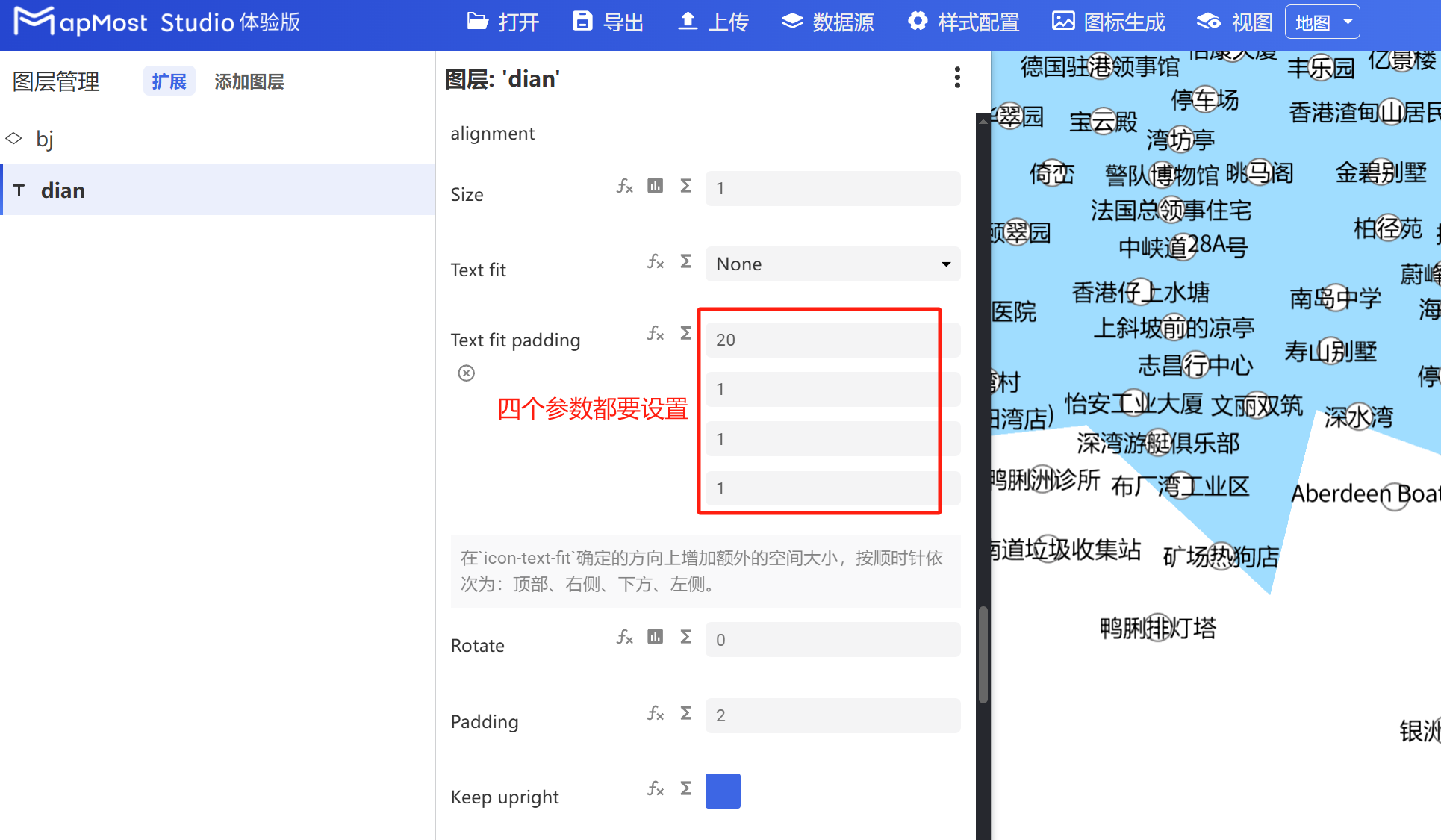
5.8. "Text fit padding" parameter setting
- The "Text fit padding" parameter sets the upper and lower margins of the icon, which is often used to control the upper and lower margins of the text box;
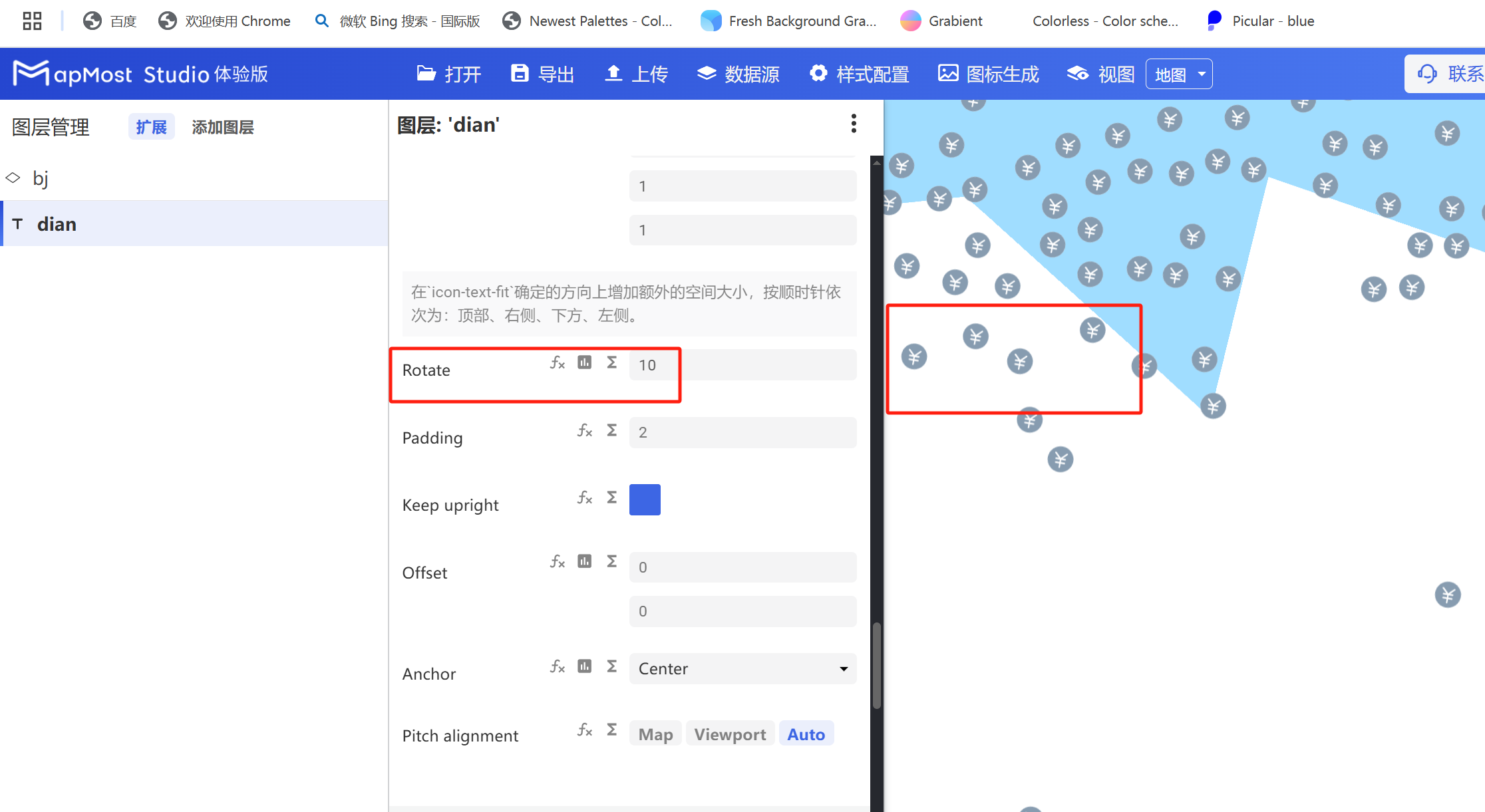
5.9. "Rotation" parameter setting
- "Rotation" parameter, set icon rotation;
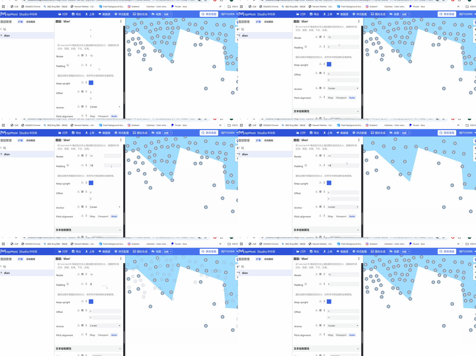
5.10. "Padding" parameter setting
- The "Padding" parameter sets the size of the space occupied by the icon and can be used to control the icon display density;
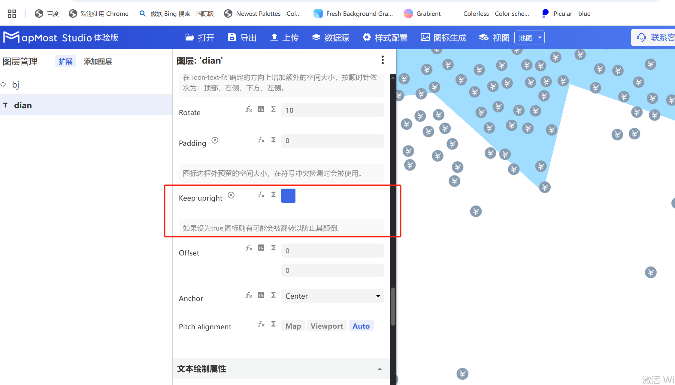
5.11. "Keep upright" parameter setting
- "Keep upright" parameter, refer to "Icon Point Layer Symbol: 3.17";
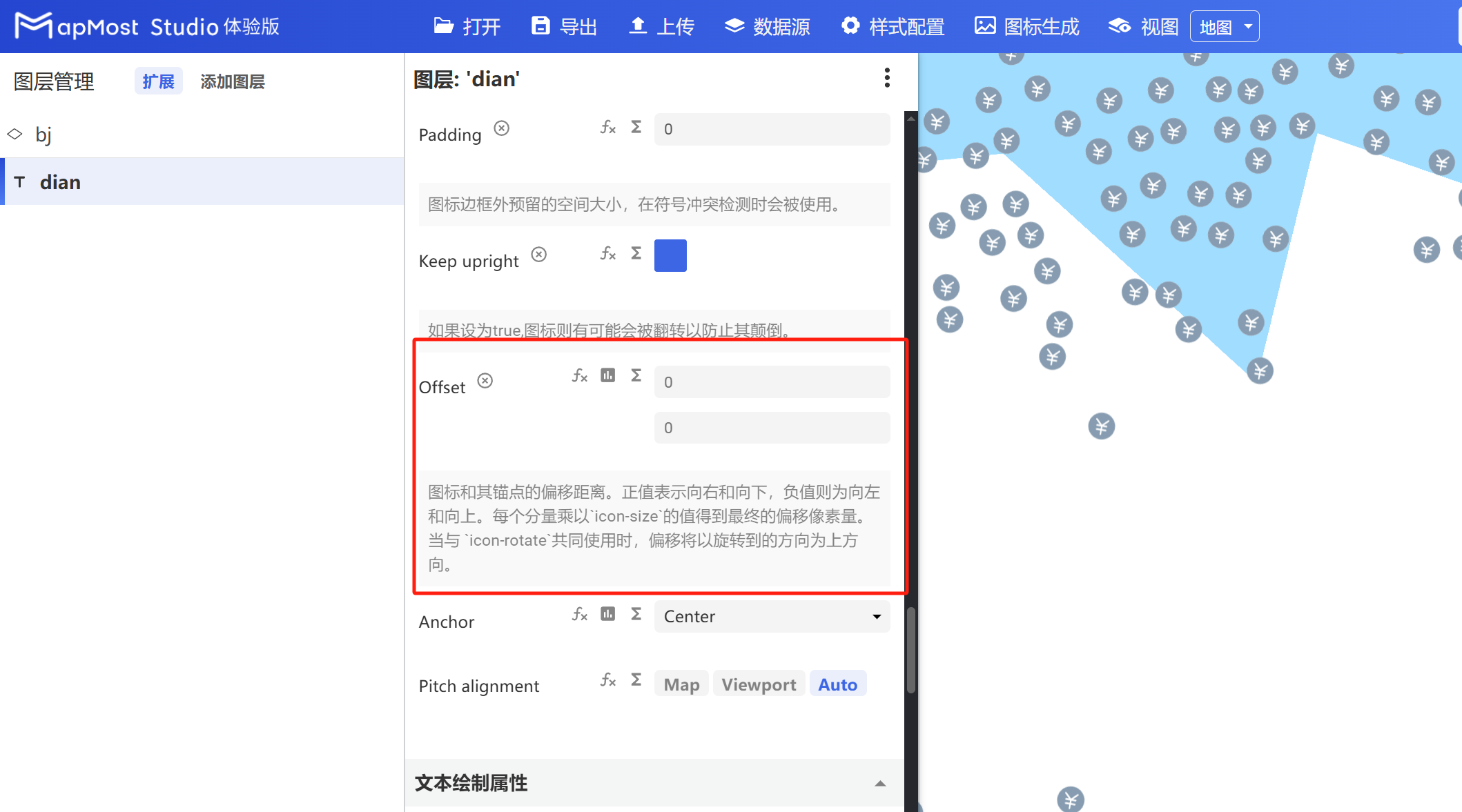
5.12. "Offset" parameter setting
- "Offset" parameter, refer to "Icon Point Layer Symbol: 3.19";
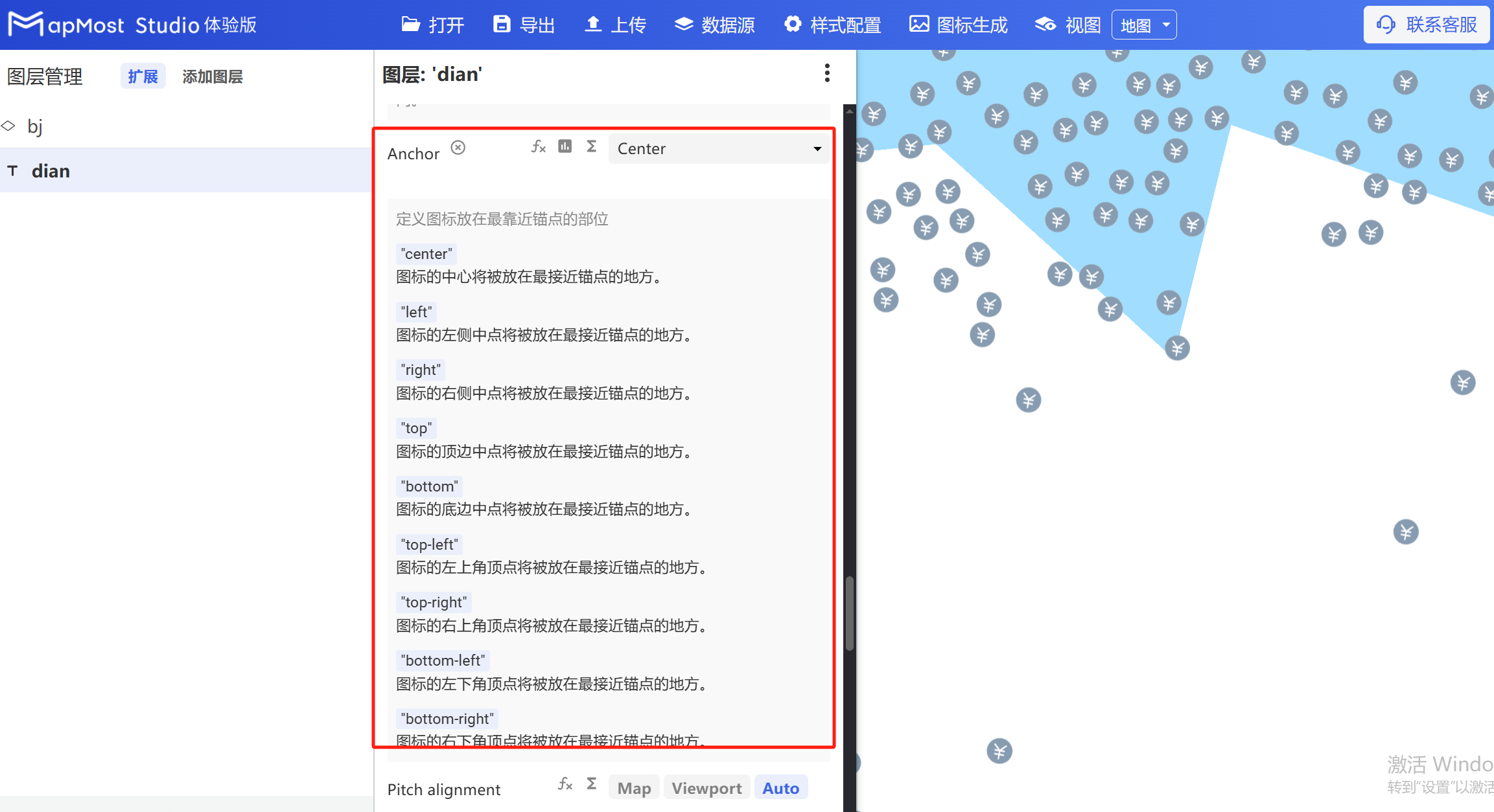
5.13. "Anchor" parameter setting
- "Anchor" parameter, refer to "Icon Point Layer Symbol: 3.13";
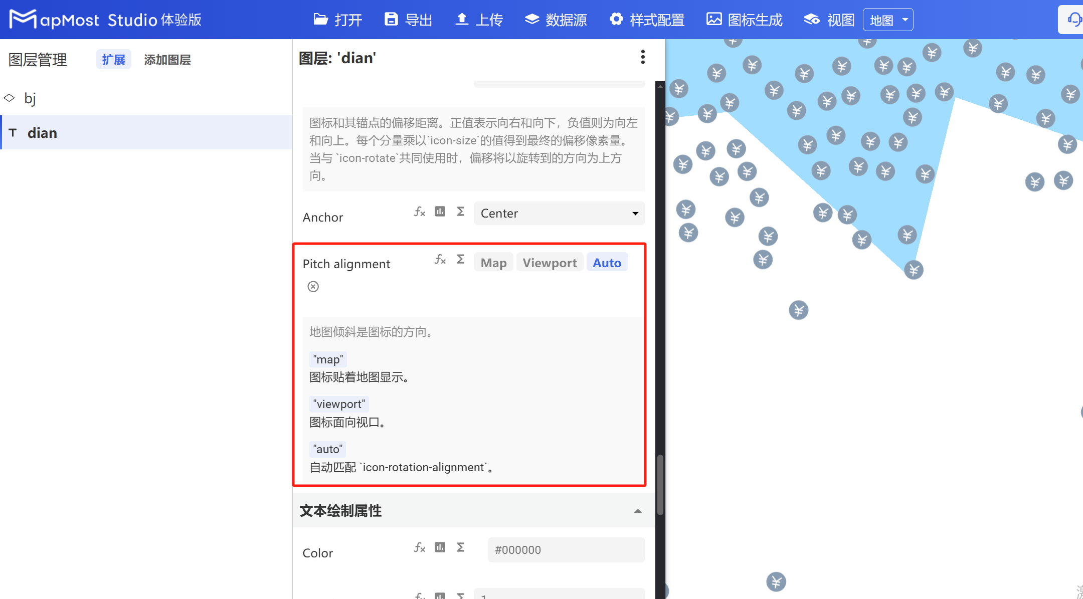
5.14. "Pitch alignment" parameter setting
- "Pitch alignment" parameter, refer to "Icon Point Layer Symbol: 3.8";
6. "Text Drawing Properties" module
The "Text Drawing Properties" module is used to set text color, transparency, stroke and other parameters.
The initial interface is as follows:
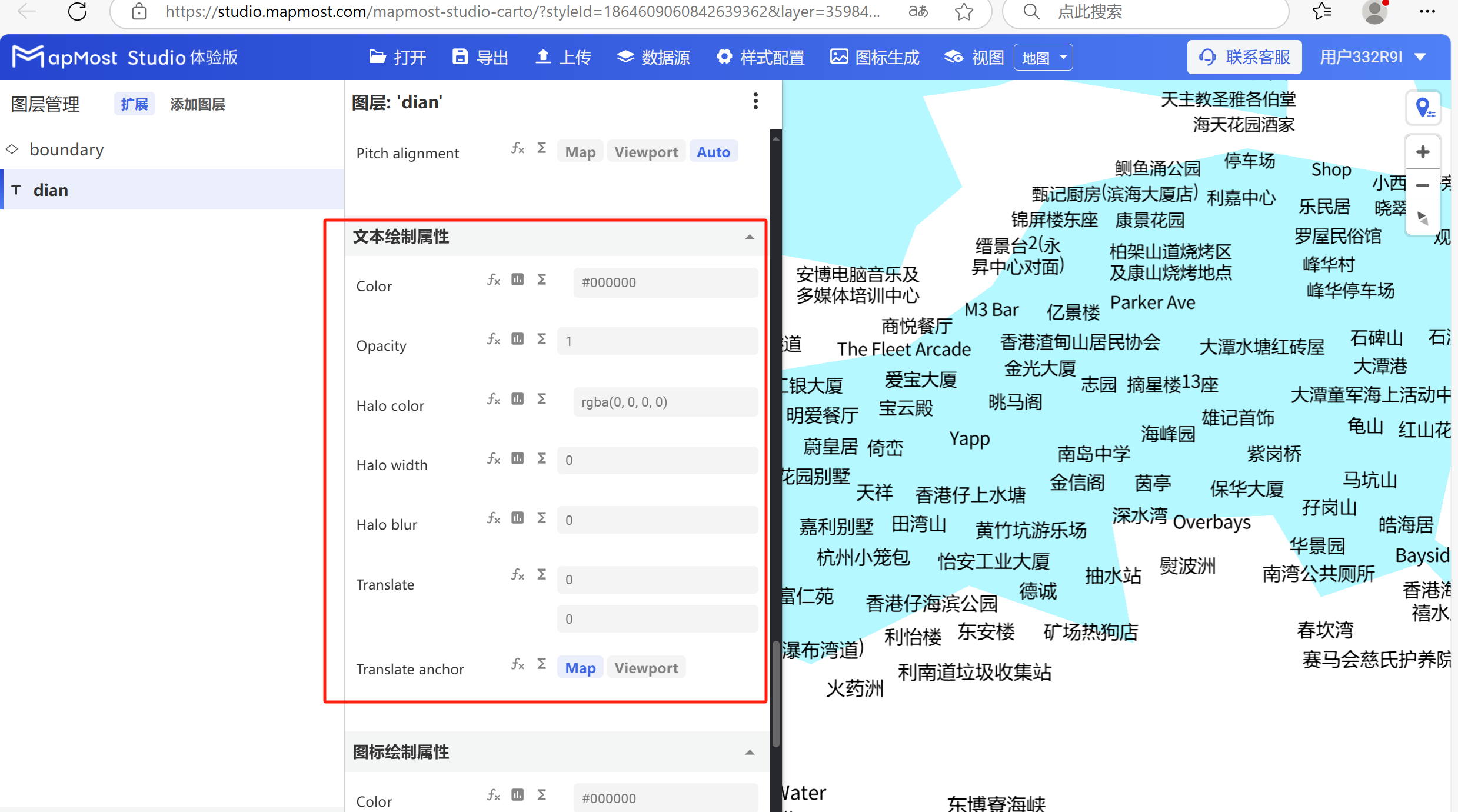
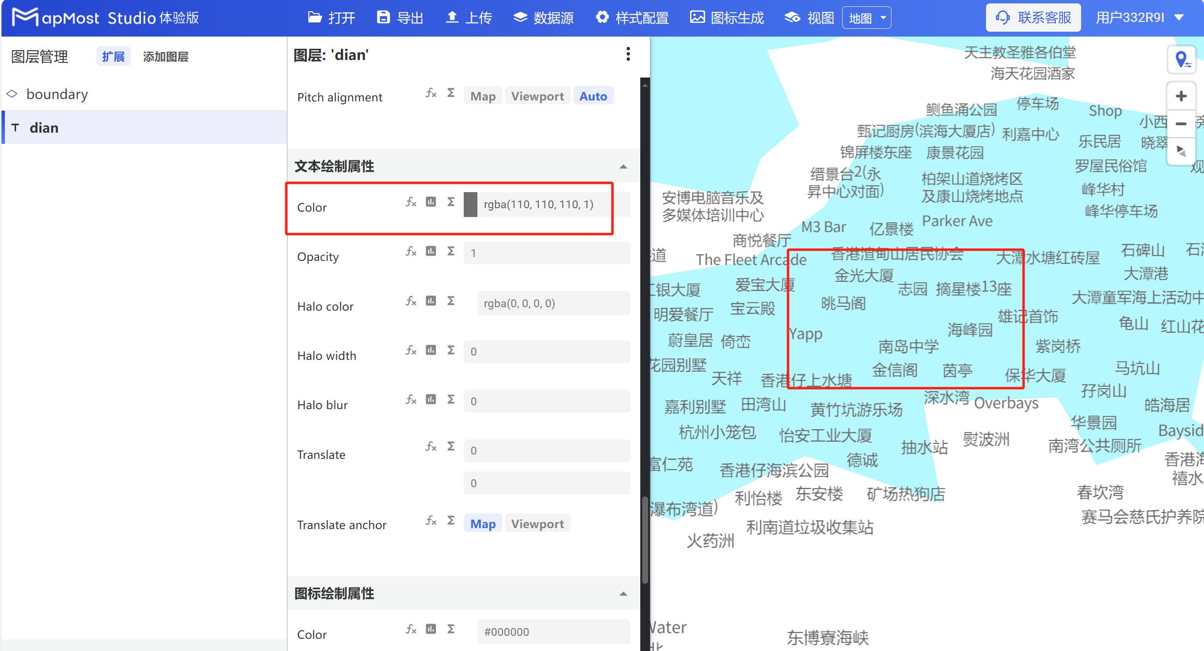
6.1. "Color" parameter setting
- "Color" parameter, set the text color;
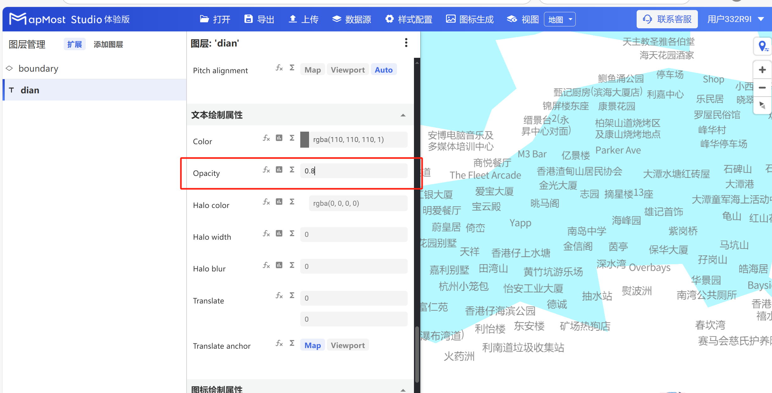
6.2. "Opacity" parameter setting
- "Opacity" parameter, sets text transparency;
6.3. "Halo color" parameter setting
- "Halo color" parameter, set the text stroke color;
6.4. "Halo width" parameter setting
- "Halo width" parameter, sets the text stroke thickness;
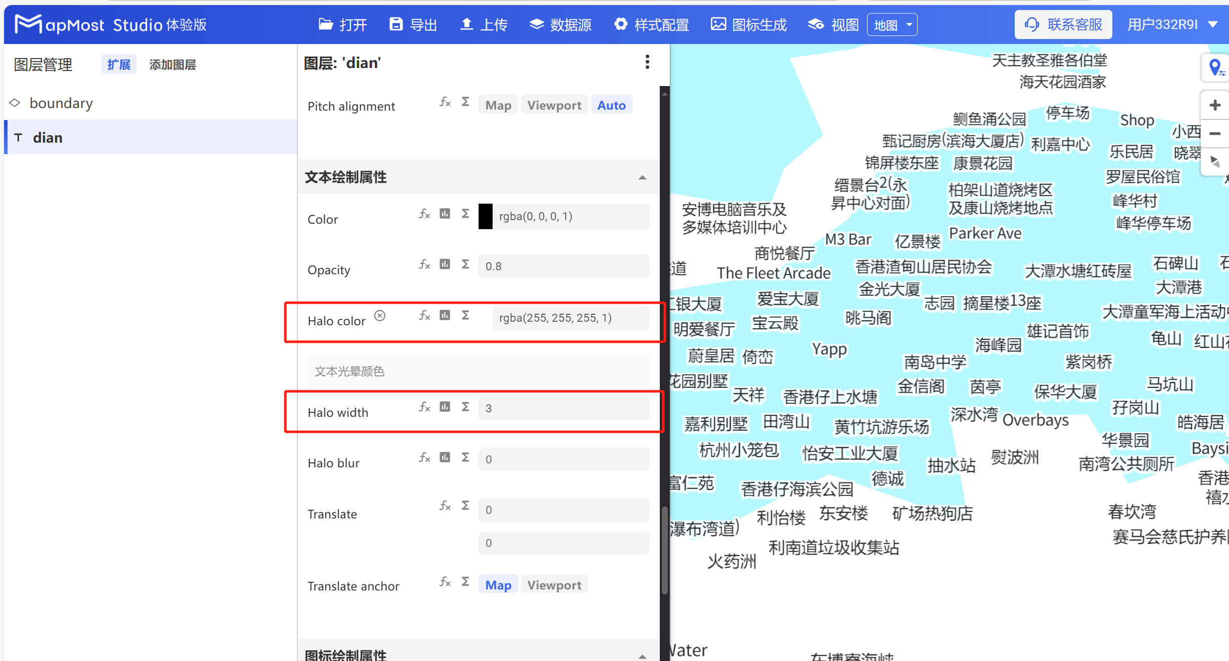
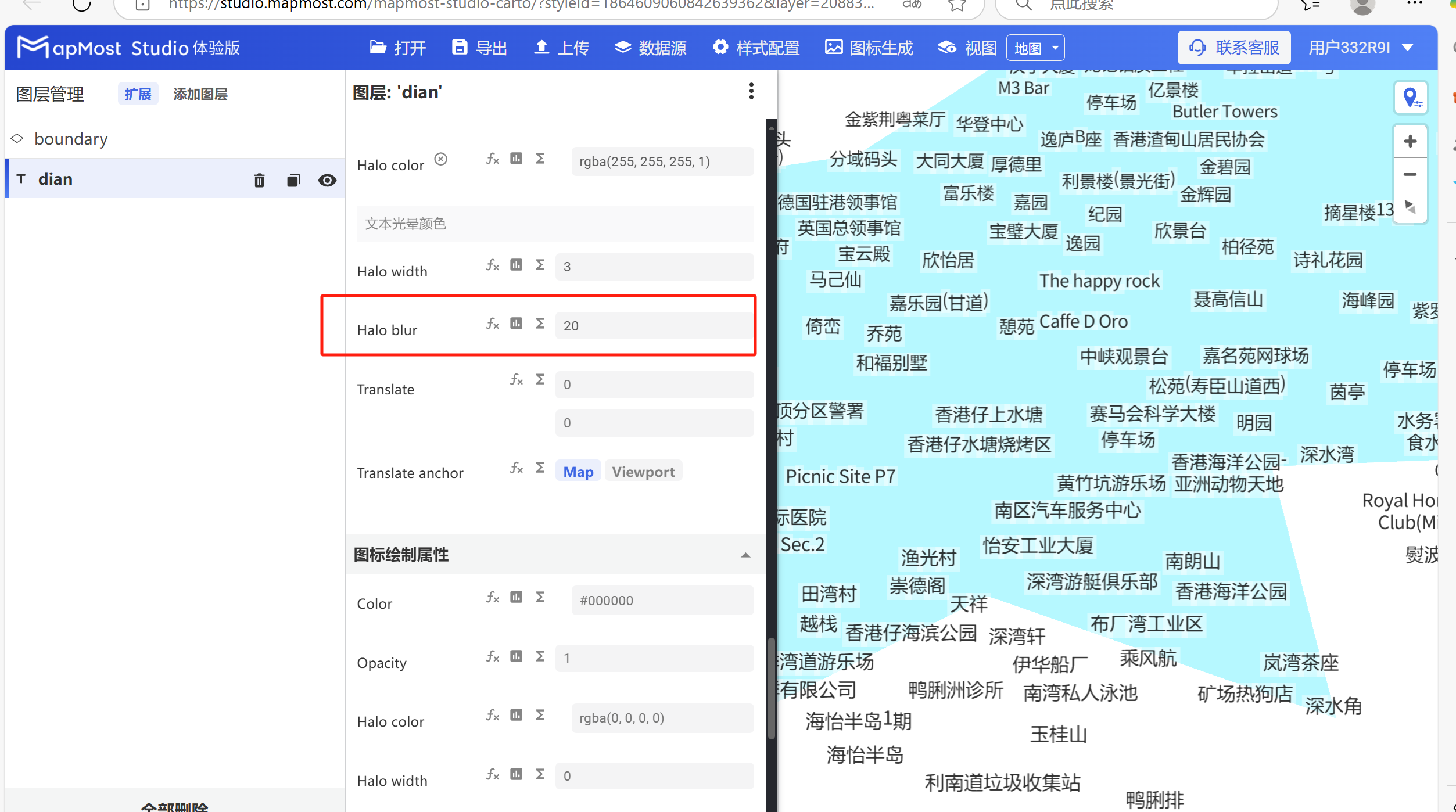
6.5. "Halo blur" parameter settings
- "Halo blur" parameter, set the stroke blur;
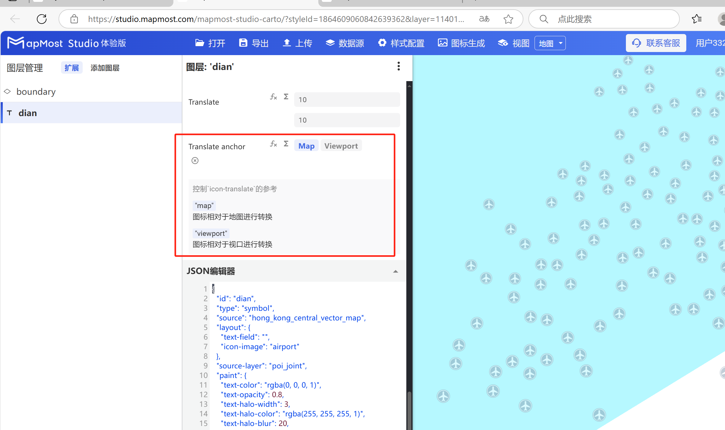
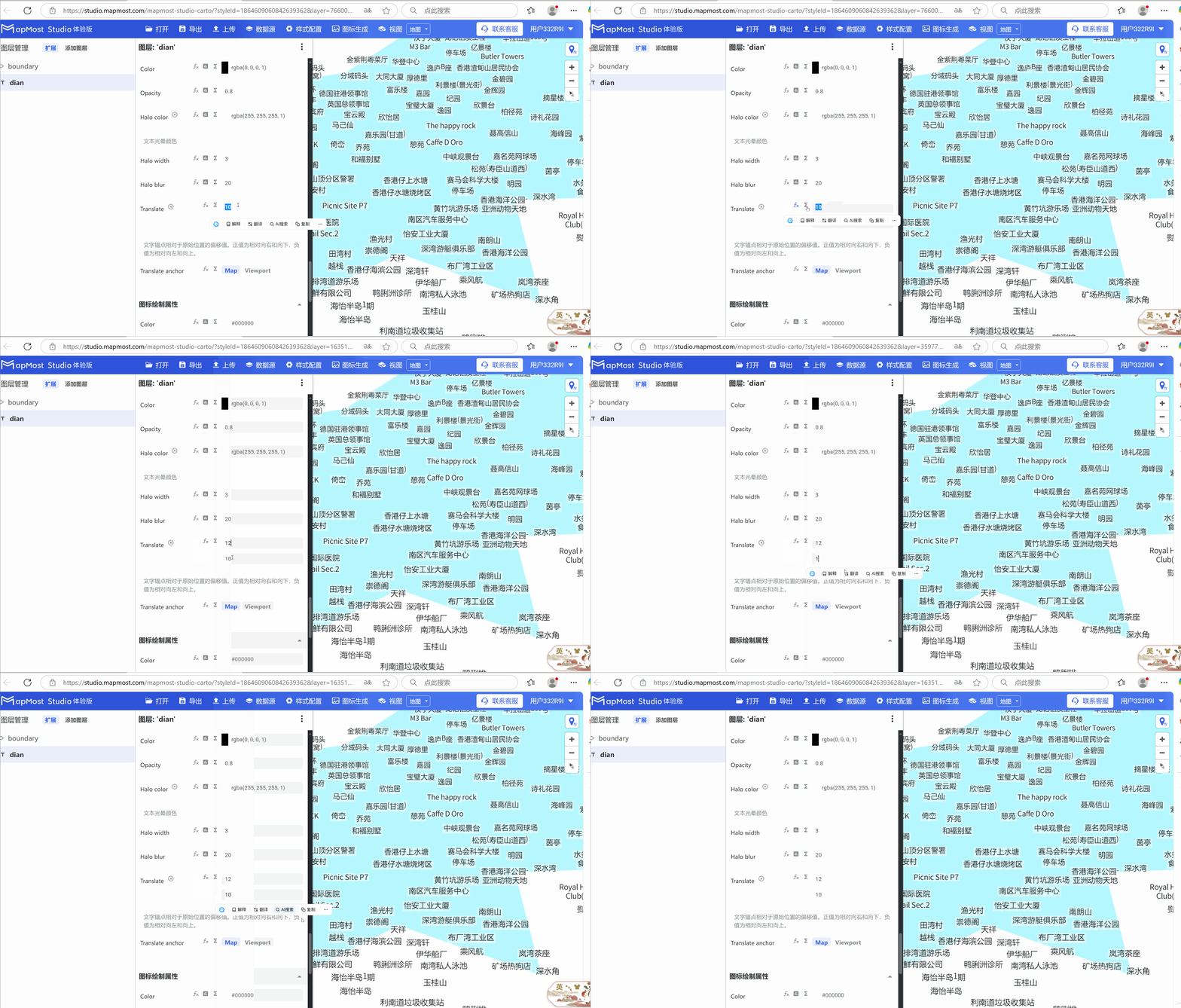
6.6. "Translate" parameter setting
- The "Translate" parameter sets the upward offset of the text relative to the X\Y axis of the anchor point;
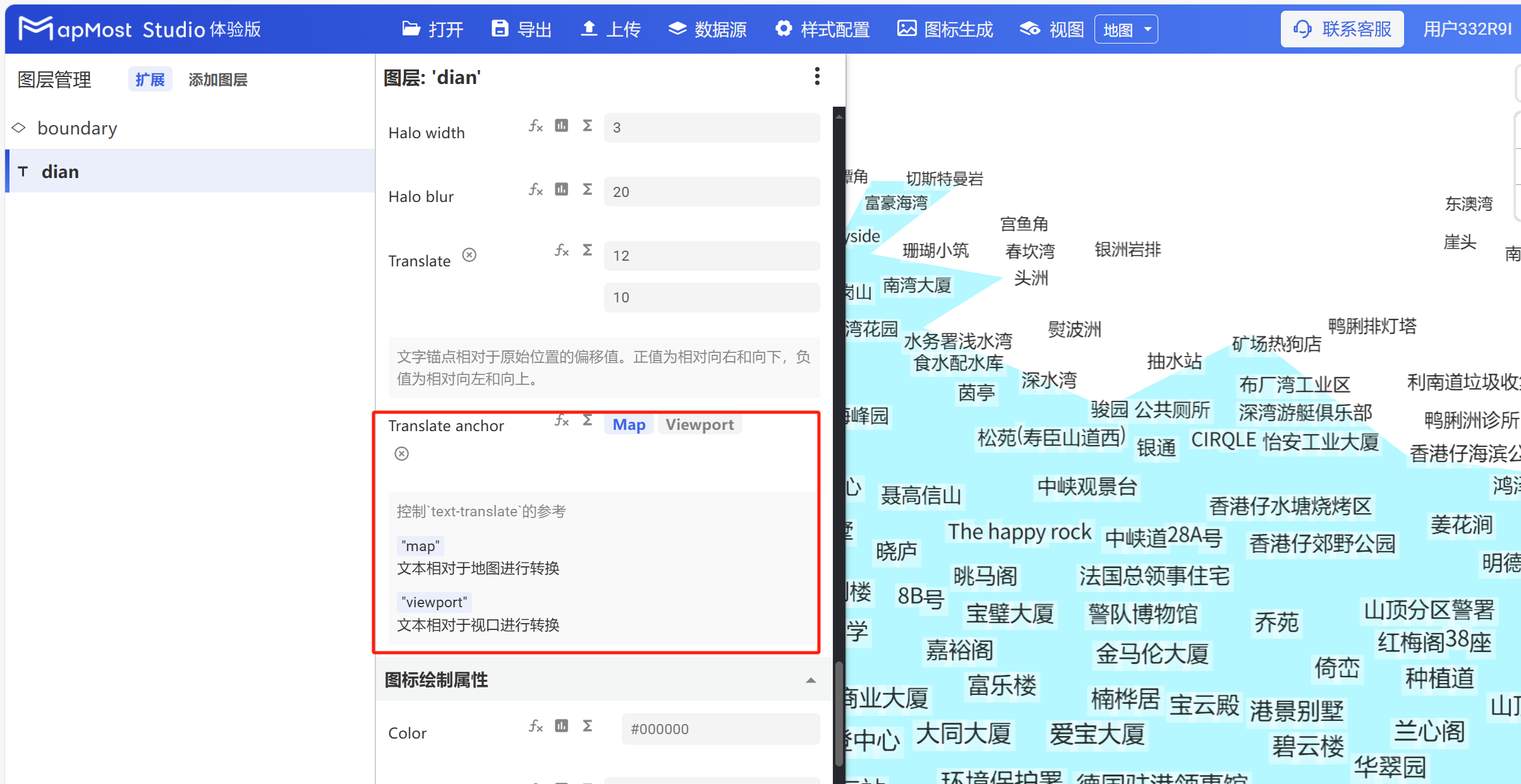
6.7. "Translate anchor" parameter setting
- The "Translate anchor" parameter sets the text conversion method, "Map" is converted relative to the map, and "Viewport" is converted relative to the viewport;
7. "Icon drawing properties" module
The "Icon Drawing Properties" module is used to set icon offset and alignment.
The initial interface is as follows:
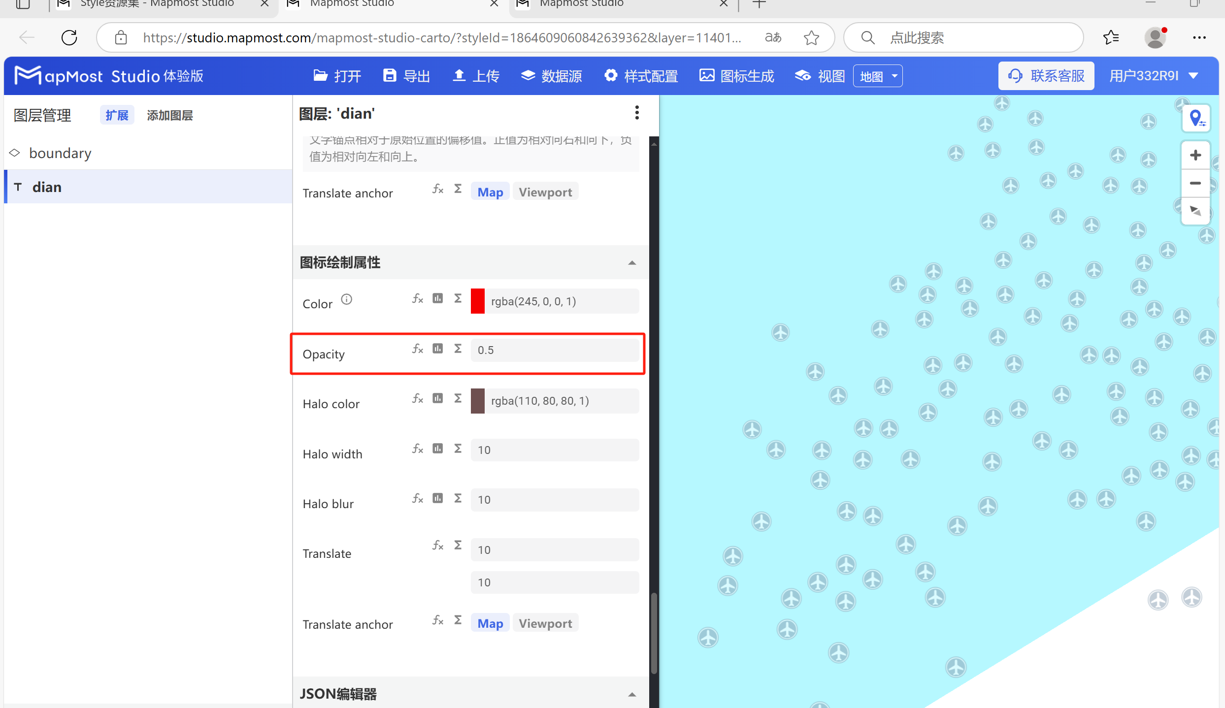
7.1. "Opacity" parameter setting
- "Opacity" parameter, adjust icon transparency;
7.2. "Translate" parameter setting
- "Translate" parameter, refer to "Icon Point Layer Symbol: 6.6";
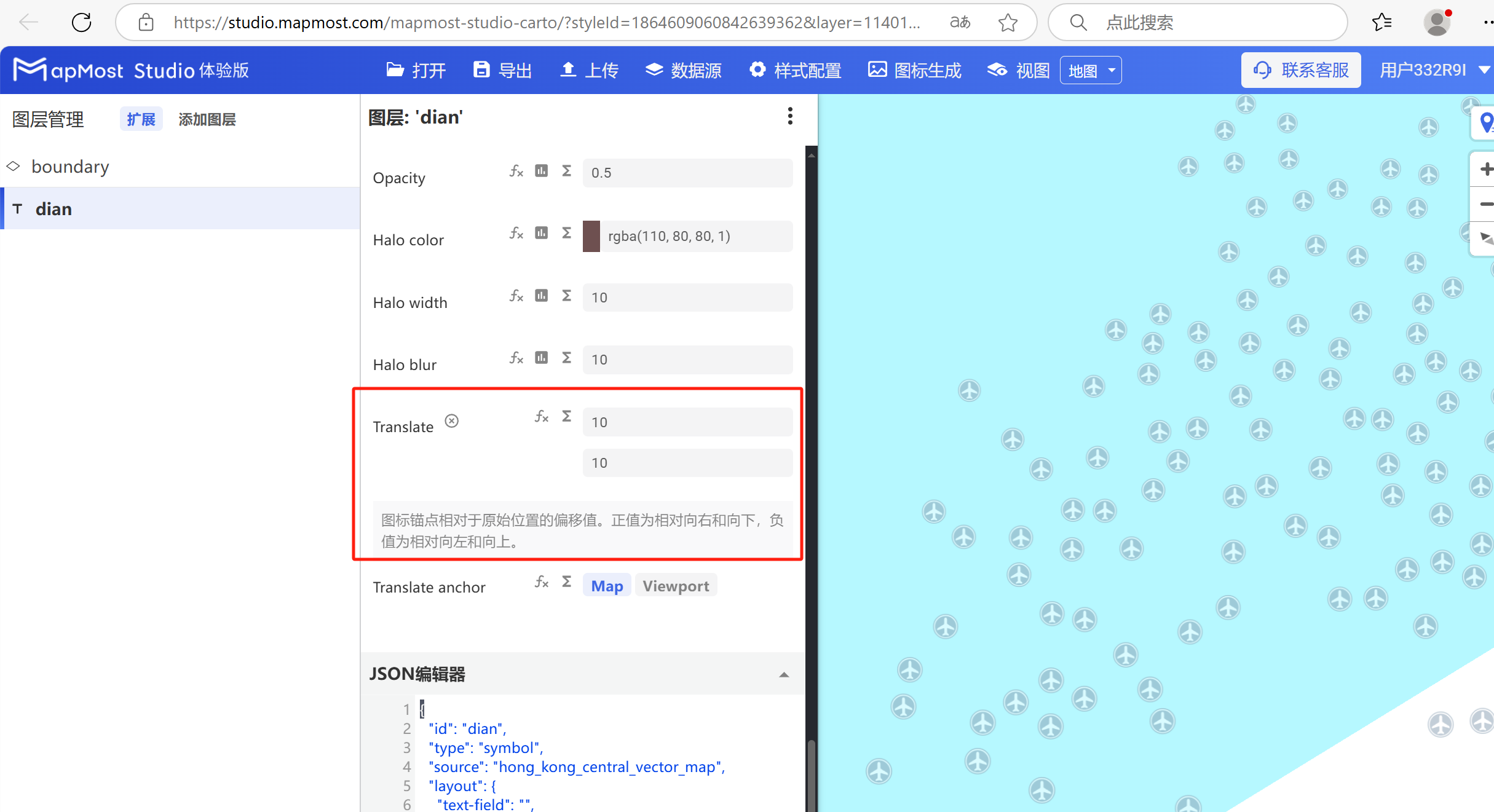
7.3. "Translate anchor" parameter setting
- "Translate anchor" parameter, refer to "Icon Point Layer Symbol: 6.7";